Using the offset face tool for midsurface modeling | |||||
|
| ||||
In addition to the basic task of creating new shell faces, the offset face tool offers two functions that are helpful for creating a midsurface model:
The offset distance is used by Abaqus/CAE to assign a thickness to the new shell faces.
The auto trim option automatically trims the new faces to the reference representation.
Once you have selected the faces to offset, you can enter a value for the offset distance or select a set of target faces that represents the distance through the desired shell thickness and have Abaqus/CAE calculate an offset. Abaqus/CAE calculates the distance between faces being offset and the target faces. You can offset to half the average distance or a fraction of the distance to the closest or farthest point on the target faces.
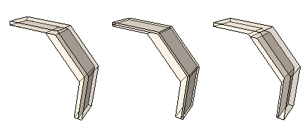
The difference in using each of the calculated offset distances is shown in Figure 1. The part has three different thicknesses. The thinnest face is at the top, the thickest in the middle, and the vertical face on the right has a thickness between the other two. The three outer faces of the reference representation were selected to be offset, and the three inner faces are the target faces. The view on the left shows the default Half the average distance method, and the offset is approximately the full thickness of the top face. The middle view shows the Fraction distance to closest point on face method with the fractional distance set to 0.5. The top target face is closest to the top offset face, so Abaqus/CAE offsets the new faces by 0.5 times this distance. The view on the right shows the Fraction distance to farthest point on face method with the fractional distance again set to 0.5. The middle (angled) target face is farthest from the middle offset face, so Abaqus/CAE offsets the new faces by 0.5 times this distance—notice that the top offset face is cut off where it would extend through the reference representation of the original solid part because the Auto trim to reference representation option was used.

Abaqus/CAE automatically associates the new offset shell faces with a thickness based on the offset calculations. If you selected target faces to calculate the offset distance, Abaqus/CAE also automatically recalculates the offset for any changes in the geometry of the top and bottom face sets. Use the Assign Thickness and Offset tool and the Render shell thickness option to edit and view the thicknesses assigned to the shell faces. For more information, see Assigning thicknesses and offsets, and Visualizing shell thicknesses.
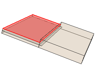
If you use the auto trim option while offsetting faces, Abaqus/CAE offsets the faces and extends the outer edges of the new faces by an amount equal to the offset distance. The new faces are then trimmed where they intersect with the reference representation. Figure 2 shows a possible effect of using the auto trim option. The reference representation contains two cells, and the highlighted face at the top of the thinner cell was picked for the offset operation. Using the auto trim option, the new face extends into the second cell of the reference representation.

In this case the picked face could be offset without the trim option to create the offset without otherwise altering the geometry. Alternatively, you could extend the offset face (extend faces tool) to fill the entire reference representation, creating a single face for both cells.