Defining Symmetry Conditions

You can use different Symmetry Conditions for obtaining symmetrical results using non-symmetrical meshes, saving the processing time for the FE-calculation. Furthermore, symmetrical load case can often be reduced in the FE model.

Important: The FE meshes do not have to be symmetric. The restriction can also be applied to unstructured meshes or to tetrahedron meshes. The elements should have nearly the same size because the result is the resolution of the coarsest part of the mesh. It is possible that the linked elements are not determined correctly if the size of the elements differs too much.

This task shows you how to:

Related Topics
In Other Guides
DVCON_TOPO
LINK_TOPO

Define Symmetry Conditions in Tosca ANSA® environment

  1. Choose DV_CONSTRAINTS and select New > SYMMETRY_CONTROL.

  2. In order to define a symmetry condition, enter following settings in the SYMMETRY_CONTROL dialog:

    • Reflection symmetry (TYPE = PLANE_SYM): the symmetry plane is identified by a point (ORIGIN_1..ORIGIN_3) and the normal direction (DIRECTION_1..DIRECTION_3).
    • Rotation symmetry (TYPE = ROTATION_SYM): the rotation axis is defined by a point (ORIGIN_1..ORIGIN_3) and the direction (DIRECTION_1..DIRECTION_3); the field ANGLE is the rotation angle.
    • Cyclic symmetry (TYPE = CYCLIC_SYM): the translation direction is defined by a point (ORIGIN_1..ORIGIN_3) and the direction (DIRECTION_1..DIRECTION_3); the field TRANSLATION is the translation distance.

    Note: Although the origin has no influence, it should be specified because SIMULIA Tosca Structure requires that the direction is an axis of a coordinate system. In this case, this coordinate system is created automatically by Tosca ANSA® environment.


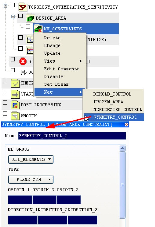
    In each case, EL_GROUP is the element group that the symmetry condition applies to.

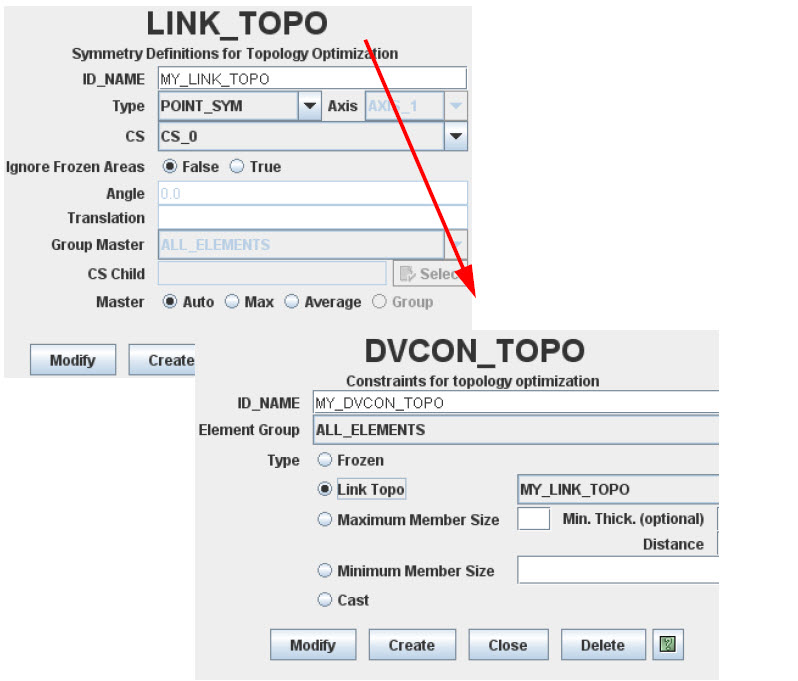
Define Symmetry Conditions in Tosca Structure.gui

  1. Choose Command > LINK_TOPO.

  2. In the LINK_TOPO menu, define the type of symmetry, the coordinate system and, if necessary, the rotation angle (in case of rotation symmetry) or the translation distance (in case of cyclic symmetry).

  3. The symmetry definition can also be extended to frozen areas by selecting the corresponding checkbox.

    The frozen elements of one area are also considered as frozen for the linked areas if Frozen checkbox is checked.

  4. Select Command > DVCON_TOPO.

  5. In the DVCON_TOPO dialog, apply the defined LINK_TOPO to an element group as shown in the following figure:


  6. The corresponding parameter file looks like:

    LINK_TOPO
     ID_NAME = <Name of LINK_TOPO object>
     CS = <Name of the reference coordinate system>
     TYPE = <Type of symmetry>, <axis>
     TRANSLATION = <Translation for cyclic symmetry>
     ANGLE = <Segment angle for rotation symmetry>
    END_
    
    
    DVCON_TOPO
     ID_NAME = <Name of DVCON_TOPO object>
     EL_GROUP = <Element group to be restricted>
     CHECK_TYPE = LINK_TOPO
     CHECK_LINK = <Name of LINK_TOPO definition>
    END_
    

    More than one symmetry condition can be defined for an element group. Geometrically, different combinations have to be feasible.