Rigid body constraint | ||
| ||
ProductsAbaqus/StandardAbaqus/Explicit
Elements tested
S4R
![]()
Features tested
Use of rigid bodies with TIE and PIN node sets to define boundary conditions for a deformable body.
![]()
Problem description
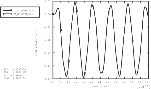
Rigid body node sets are defined to contain all nodes along the edges of a rectangular plate modeled with shell elements. The rigid body reference node is constrained against all rotations and - and -displacements. A saw-tooth velocity pattern acting in the z-direction is applied at the reference node of the rigid body. Starting at 0 m/s, the velocity is ramped down to −10 m/s at time 2.0 × 10⁻³ s and is ramped back to 0 m/s at time 6.0 × 10⁻³ s. Thereafter, the analysis is continued up to time 48.0 × 10⁻³ s. The following three cases are considered:
A rigid body TIE NSET is defined to contain all the edge nodes. The results are compared to the solution of the same problem with the rigid body TIE NSET replaced with equivalent boundary conditions applied at the edge nodes.
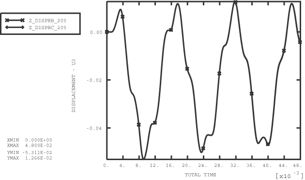
A rigid body PIN NSET is defined to contain all the edge nodes. The results are compared to the solution of the same problem with the rigid body PIN NSET replaced with equivalent boundary conditions applied at the edge nodes.
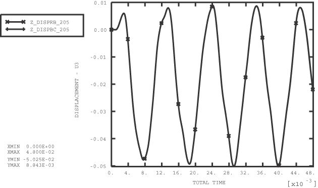
A rigid body TIE NSET is defined to contain all the nodes along two opposite edges of the plate. The remaining edge nodes are included in a PIN NSET. The results are compared to the solution of the same problem with the rigid body TIE and PIN node sets replaced with equivalent boundary conditions applied at the edge nodes.
![]()
Results and discussion
The plate displaces in response to the applied velocities at the boundary nodes and continues vibrating after the velocities at the boundary nodes have been ramped down to zero. The time variation of the -displacement at node 205 at the center of the plate is plotted in Figure 1 for Case 1. Following an initial lag, the center node vibrates in response to the boundary motion. The solution obtained using rigid body TIE NSET is found to match closely with the results of the same problem solved with the rigid body TIE NSET replaced by equivalent boundary conditions specified directly at the edge nodes. Similar conclusions can be drawn from Figure 2 for Case 2 and Figure 3 for Case 3.
![]()
Input files
Abaqus/Standard analysis
- rigboun1_std.inp
-
Case 1.
- rigboun1bc_std.inp
-
Comparison test of Case 1.
- rigboun2_std.inp
-
Case 2.
- rigboun2bc_std.inp
-
Comparison test of Case 2.
- rigboun3_std.inp
-
Case 3.
- rigboun3bc_std.inp
-
Comparison test of Case 3.
Abaqus/Explicit analysis
- rigboun1.inp
-
Case 1.
- rigboun1bc.inp
-
Comparison test of Case 1.
- rigboun2.inp
-
Case 2.
- rigboun2bc.inp
-
Comparison test of Case 2.
- rigboun3.inp
-
Case 3.
- rigboun3bc.inp
-
Comparison test of Case 3.
![]()
Figures