Pressure penetration loading with surface-based contact | ||||||
|
| |||||
ProductsAbaqus/Standard
A single slave node–based penetration criterion is used. Fluid penetrates into the surface between the contacting bodies from one or multiple locations, which are exposed to the fluid, until a point is reached where the contact pressure is greater than the critical value specified by the user, cutting off further penetration of the fluid. The critical contact pressure is introduced to account for the asperities on the contacting surfaces. The higher this value, the easier the fluid penetrates. The default value of the critical contact pressure is zero, in which case fluid penetration occurs only if the contact pressure is zero and contact is lost. The nodes initially exposed to the fluid, which are specified by the user, are always subjected to the fluid pressure irrespective of the contact status at these nodes.
The pressure penetration load is applied normal to surface faces in the wetted region based on the pressure penetration criterion described above at the beginning of an increment and remains constant over that increment even if the fluid penetrates further during that increment. For two-dimensional models the pressure acting on a given face of the slave surface is uniform, except for the surface faces adjacent to the wetted region. A nondefault option can be chosen so that the pressure ramps off across these surface faces. For three-dimensional models the only option is for the pressure to ramp off across the surface faces adjacent to the wetted region.
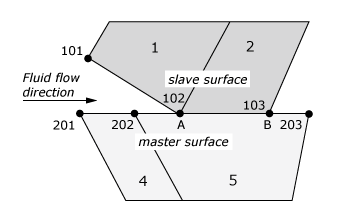
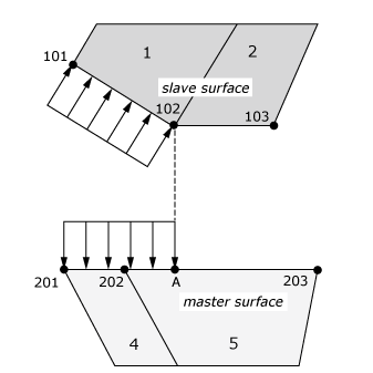
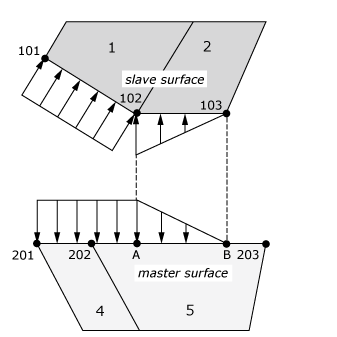
Consider the contact interaction of three nodes—101, 102, and 103—on the slave surface made up of faces of two first-order elements, 1 and 2, with a master surface made up of faces of two elements, 4 and 5, which are described by nodes 201, 202, and 203, as shown in Figure 1. The pressure-penetration load acting on the master surface faces corresponds to the projection of the pressure distribution of the slave surface. Point A corresponds to where node 102 projects to the master surface, and point B corresponds to where node 103 projects to the master surface. If a fluid with a pressure magnitude of f has penetrated up to node 102 on the slave surface, pressure loads are applied as follows:
- For a two-dimensional model, by default, a uniform pressure f acts on the slave surface face associated with element 1 and to the left of point A on the master surface, as shown in Figure 2.
- For a two-dimensional model using the nondefault option or for a three-dimensional model, the fluid pressure distribution is as shown in Figure 3, which differs from Figure 2 by the addition of linearly ramped portions on the slave surface face of element 2 and on the corresponding region from point A to point B of the master surface. This behavior is such that the pressure partially acts past node 102, where the contact pressure criteria for further propagation is evaluated, which can strongly influence the contact pressure calculated at this location.


