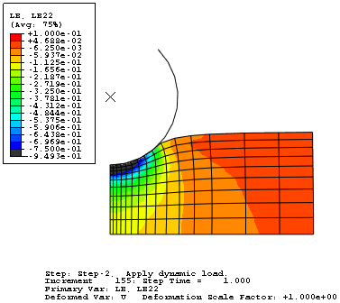
Display the contour plot at the end of the last increment of the second step (Step 2 and Step Time = 1.000).
From the main menu bar, select .
Abaqus displays the Contour Plot Options dialog box.
Click the Basic tab if it is not already selected, and drag the uniform contour intervals slider to 16.
Click the Limits tab to access the contour limits options.
- In the Max field, toggle the Specify button and type a maximum contour limit of 0.1.
- In the Min field, toggle the Specify button and type a minimum of −0.75.
Click Apply to view the customized contour plot.
The plot changes, as shown in Figure 1.
Figure 1. Customized contour plot.

Although you selected 16 contour intervals, the plot legend displays 17 intervals. Abaqus adds intervals to indicate any values that are greater than the maximum contour limit or less than the minimum contour limit and displays these values in light gray and dark gray, respectively. In this example, areas undergoing compressive strains greater than 0.75 are shown in dark gray. The minimum strain in the model is shown at the bottom of the contour legend. You might use either of these colors to indicate elements that fall outside the design range for the selected variable.
Under the Limits tab, examine the Min and Max Auto-compute options.
The minimum and maximum values of strain for the contour plot are shown next to the two Auto-compute options.
Toggle on Show location for the Min/Max options to display the locations in the model where the extreme values occur.
Click OK to close the Contour Plot Options dialog box.