Determining the peak pull-out force

To find the peak pull-out force at the attachment points, create an X–Y plot of the reaction force in the 1-direction (variable RF1) at the attached nodes. This involves plotting multiple curves at the same time.

This task shows you how to:

Plot multiple curves

  1. In the Results Tree, click mouse button 3 on History Output for the output database named DynCrane.odb. From the menu that appears, select Filter.

  2. In the filter field, enter *RF1* to restrict the history output to just the reaction force components in the 1-direction.

  3. From the list of available history output, select the four curves (using CtrlClick) that have the following form:

    Reaction Force: RF1 PI: TRUSS-1 Node xxx in NSET ATTACH

  4. Click mouse button 3, and select Plot from the menu that appears.

    Abaqus/CAE displays the selected curves.

  5. Click in the prompt area to cancel the current procedure.

Position the grid

  1. Double-click the plot to open the Chart Options dialog box.

  2. In this dialog box, switch to the Grid Area tabbed page.

  3. In the Size region of this page, select the Square option.

  4. Use the slider to set the size to 75.

  5. In the Position region of this page, select the Auto-align option.

  6. From the available alignment options, select the last one (position the grid in the lower right corner of the viewport).

  7. Click Dismiss.

Position the legend

  1. Double-click the legend to open the Chart Legend Options dialog box.

  2. In this dialog box, switch to the Area tabbed page.

  3. In the Position region of this page, toggle on Inset.

  4. To display the minimum and maximum values in the legend, switch to the Contents tabbed page of the dialog box. In the Numbers region of this page, toggle on Show min/max.

  5. Click Dismiss.

  6. Drag the legend in the viewport to reposition it.

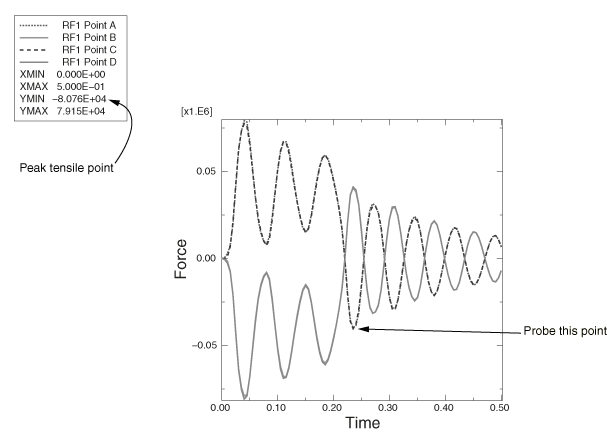
    The resulting plot (which has been customized) is shown in Figure 1. The curves for the two nodes at the top of each truss (points B and C) are almost a reflection of those for the nodes on the bottom of each truss (points A and D).

    Note:

    To modify the curve styles, click in the Visualization toolbox to open the Curve Options dialog box.

    Figure 1. History of the reaction forces at the attached nodes.

Query the X–Y plot

Context:

At the attachment points at the top of each truss structure, the peak tensile force is around 80 kN, which is below the 100 kN capacity of the connection. Keep in mind that a negative reaction force in the 1-direction means that the member is being pulled away from the wall. The lower attachments are in compression (positive reaction force) while the load is applied but oscillate between tension and compression after the load has been removed. The peak tensile force is about 40 kN, well below the allowable value. To find this value, probe the X–Y plot.

  1. From the main menu bar, select ToolsQuery.

    The Query dialog box appears.

  2. Click ToolsQuery in the Visualization Module Queries field.

    The Probe Values dialog box appears.

  3. Select the point indicated in Figure 1.

    The Y-coordinate of this point is –40.30 kN, which corresponds to the value of the reaction force in the 1-direction.