Copy the existing model to a model named
Frequency. Make all of the following changes
to the Frequency model. In the frequency
extraction analysis you will replace all existing steps with a single frequency
extraction step. In addition, you will delete all of the rigid body tools and
contact interactions; they are not necessary for determining the fundamental
frequency of the blank.
Add a density of 7800 to the material
model Steel.
Delete the die, holder, and punch part instances. These rigid parts
are not necessary for the frequency analysis.
Replace the existing steps with a single frequency extraction step.
-
Delete the step Move punch.
-
In the
Model Tree,
click mouse button 3 on the step Holder force
and select Replace from the menu that appears.
-
In the Replace Step dialog box, select
Frequency from the list of available Linear
perturbation procedures. Enter the step description
Frequency modes; select the Lanczos
eigensolver option; and request five eigenvalues. Rename the step
Extract Frequencies.
-
Suppress the DOF Monitor.
Note:
Since the frequency extraction step is a linear perturbation
procedure, nonlinear material properties will be ignored. In this analysis the
left end of the blank is constrained in the
x-direction and cannot rotate about the normal;
however, it is not constrained in the y-direction.
Therefore, the first mode extracted will be a rigid body mode. The frequency of
the second mode will determine the appropriate time period for the quasi-static
analysis in
Abaqus/Explicit.
Delete all contact interactions.
Open the Boundary Condition Manager, and examine
the boundary conditions in the Extract
Frequencies step. Delete all boundary conditions except the
boundary condition named CenterBC. This leaves
the blank constrained with a symmetry boundary condition applied to the left
end.
Remesh the blank if necessary.
Create a job named Forming-Frequency
with the following job description: Channel forming --
frequency analysis. Submit the job for analysis, and monitor
the solution progress.
When the analysis is complete, enter
the Visualization module
and open the output database file created by this job. From the main menu bar,
select ; or use the
 tool in the toolbox.
The deformed model shape for the first vibration mode is plotted (it is a
rigid body mode). Advance the plot to the second mode of the blank. Superimpose
the undeformed model shape on the deformed model shape.
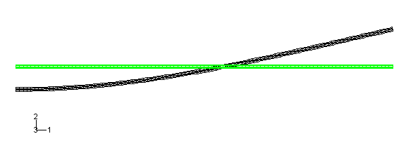
The frequency analysis shows that the blank has a fundamental frequency of
140 Hz, corresponding to a period of 0.00714 s.
Figure 1
shows the displaced shape of the second mode. We now know that the shortest
step time for the forming analysis is 0.00714 s.
Figure 1. Second mode of the blank from the
Abaqus/Standard
frequency analysis.


 tool in the toolbox.