Defining the model geometry | ||
| ||
Context:
You need to decide what system of units to use in your model. The SI system of meters, seconds, and kilograms is recommended; but you can use another system if you prefer.
In the Model Tree, double-click the Parts container to create a new part.
In the Create Part dialog box, name the part Lug and accept the default settings of a three-dimensional, deformable body and a solid, extruded base feature. In the Approximate size text field, type 0.250. This value is twice the largest dimension of the part. Click Continue to exit the Create Part dialog box.
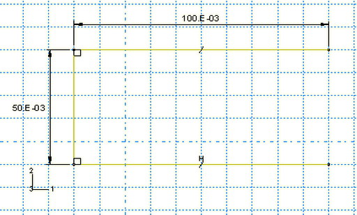
Use the dimensions given in Figure 1 to sketch the profile of the lug. The following possible approach can be used:
-
Create an arbitrary rectangle using the Create Lines:
Rectangle tool. Delete the right vertical edge, and assign an
Equal length constraint to the top and bottom edges using
the constraints tool
 . Use the dimensions tool
 to adjust the profile so that it is 0.100 m long × 0.050 m
wide, as shown in
Figure 1.
Figure 1. Open rectangle (with grid spacing doubled).
Note:
The figures in this section include dimensions and constraints for the purpose of controlling the shape of the sketch. As seen previously, these tools are accessible from the Sketcher toolbox. These tools are also accessible by selecting AddConstraint and AddDimension, respectively, from the main menu bar.
You can edit the dimension values as you add them to the sketch, or you can edit the value of existing dimensions by selecting EditDimension from the main menu bar or by using the Edit Dimension Value
 tool.
tool.
-
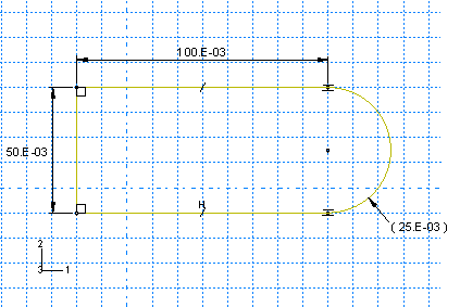
Close the profile by adding a semicircular arc, as shown in
Figure 2,
using the Create Arc: Thru 3 points tool,
 .
Figure 2. Rounded end (with grid spacing doubled).
Select the two vertices at the open end of the rectangle as the endpoints of the arc, starting with the top one. Select any point to the right of the sketch as a point that lies on the arc. Define Tangent constraints between the ends of the arc and the horizontal lines to refine the sketch. In Figure 2 the radial dimension of the arc is enclosed in parentheses, indicating that it is used only for reference purposes. To change any dimension to a reference value, simply edit the dimension and toggle on Reference in the Edit Dimension dialog box.
-
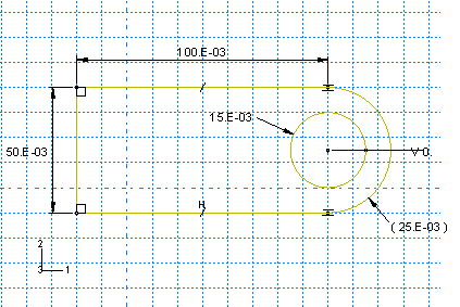
Sketch a circle of radius 0.015 m, as shown in
Figure 3,
using the Create Circle: Center and Perimeter tool,
 .
Figure 3. Lug hole (with grid spacing doubled).
Place the center of the circle to coincide approximately with the center of the arc created in the previous step. The perimeter point should be placed to the right of the center point. Apply a Concentric constraint to the arc and the circle. Use the Add Dimension
 tool to change the value of the radius to 0.015 m.
-
The perimeter points of the circles should be on the same
horizontal plane as the circle center points (as in
Figure 3).
If these points do not line up correctly, dimension the vertical distance
between the center of each circle and its perimeter point so that the distance
is 0.
Note:
When you mesh a part, Abaqus/CAE places nodes wherever vertices appear along an edge; therefore, the location of the vertex on the circumference of the circle influences the final mesh. Placing it on the same horizontal plane as the center point results in a higher quality mesh.
-
Click Done in the prompt area when you are
finished sketching the profile.
The Edit Base Extrusion dialog box appears. To complete the part definition, you must specify the distance over which the profile will be extruded.
-
In the dialog box, enter an extrusion distance of
0.020 m and click OK.
Abaqus/CAE exits the Sketcher and displays the part.
-
Create an arbitrary rectangle using the Create Lines:
Rectangle tool. Delete the right vertical edge, and assign an
Equal length constraint to the top and bottom edges using
the constraints tool