Defining beam section properties | ||
| ||
Context:
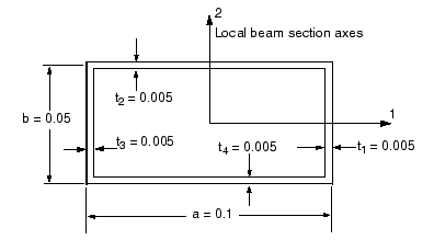
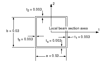
A box-section is shown in Figure 1. The dimensions shown in Figure 1 are for the main members of the two trusses in the crane. The dimensions of the beam sections for the bracing members are shown in Figure 2.
Figure 1. Cross-section geometry and dimensions (in m) of the main members.


Figure 2. Cross-section geometry and dimensions (in m) of the internal and cross bracing members.

