Context:
The bolted joints, which connect the cross bracing to the truss structures,
and the connection at the tip of the truss structures are different from the
welded joint connections. Since these joints do not provide complete continuity
for all degrees of freedom, separate vertices are needed for connection. Thus,
the cross bracing must be treated as a separate part since distinct geometric
entities are required to model the bolted joints. Appropriate constraints
between the separate vertices must be specified.
We begin by discussing a technique to define the truss geometry. Since the
two truss structures are identical, it is sufficient to define the base feature
of the part using only the geometry of a single truss structure. The sketch of
the truss geometry can be saved and then used to add the second truss structure
to the part definition.
The dimensions shown in
Figure 2
are relative to a global Cartesian coordinate system. The base feature,
however, must be sketched in a local plane. To make the sketching easier, datum
features will be used. A datum plane, parallel to one of the trusses (truss B
in
Figure 1,
for example), will serve as the sketch plane. The orientation of the sketch
plane will be defined using a datum axis.
The other truss will also be added as a planar wire feature by projecting
the truss created here onto a new datum plane.
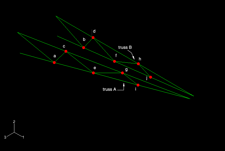
The final truss part is shown in
Figure 1.
The visibility of all datum and reference geometry has been suppressed.
Figure 1. Final geometry of the truss structures; highlighted vertices indicate
the locations of the pin joints.
Define the geometry of a single truss
To create a datum plane, a part must first be created. A part
consisting of a single reference point will serve this purpose. Begin by
creating a three-dimensional deformable part using the point base feature. Set
the approximate part size to 20.0, and name
the part Truss. Place the point at the origin.
This point represents point D in
Figure 1.
Using the Create Datum Point: Offset From Point
tool
 , create two datum points at distances of (0, 1,
0) and (8, 1.5, 0.9) from the
reference point. These points represent points C and E, respectively, in
Figure 1.
Reset the view using the Auto-Fit View tool
 in the
View Manipulation toolbar
to see the full model.
Using the Create Datum Plane: 3 Points tool
 , create a datum plane to serve as the sketch plane. Select the
reference point first, and then select the other two datum points in a
counterclockwise fashion. Click mouse button 2 to exit the procedure.
Note:
While selecting the points in this way is not
required, it will make certain operations that follow easier. For example, by
selecting the points in a counterclockwise order, the normal to the plane
points out of the viewport and the sketch plane will be oriented automatically
in the 1–2 view in the Sketcher. If you select the points in a clockwise order,
the plane's normal will point into the viewport and the sketch plane will have
to be adjusted in the Sketcher.
Using the Create Datum Axis: Principal Axis tool
 , create a datum axis parallel to the
Y-Axis. As noted earlier, this axis will be used to
position the sketch plane.
You are now ready to sketch the geometry. Use the Create
Wire: Planar tool
 to enter the Sketcher. Select the datum plane as the plane on
which to sketch the wire geometry; select the datum axis as the axis that will
appear vertical and to the left of the sketch. You may need to resize the view
to select these entities.
Once in the Sketcher, use the Sketcher Options
tool to modify the display. In the General tab, change the
Sheet size to 20 and
reduce the Grid spacing to
2. Zoom in to see the datum points more
clearly.
Note:
If the sketch plane is not oriented in the 1–2 plane,
use the
Views toolbar
to change to the X–Y view.
Using the Create Lines: Connected tool
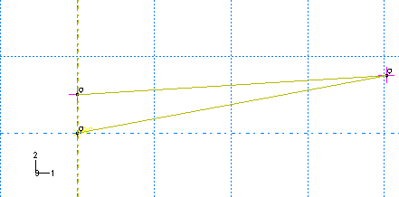
 , sketch the lines representing the main truss, as shown in
Figure 2.
The datum points that were projected are treated as fixed points in the sketch.
Any line connected to one of these points effectively inherits a fixed
constraint at that point.
Figure 2. Main members of the truss.
Next, create a series of connected lines as shown in
Figure 3
to approximate the interior bracing of the truss.
Figure 3. Rough layout of interior members.
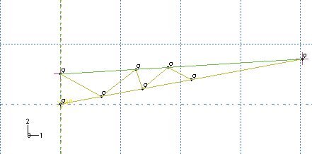
At this stage, the layout of the interior bracing is arbitrary and is
intended only as a rough approximation of the true shape. The endpoints of the
lines, however, must snap to the edges of the main truss members. This is
indicated in the figure by the presence of small circles next to the
intersections of the interior bracing with the main members. Avoid creating 90°
angles because that will introduce unwanted additional constraints.
Split the edges of the main members at the points where they intersect
the interior bracing.
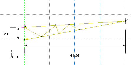
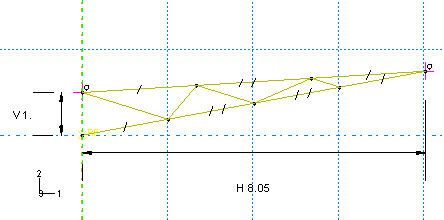
Dimension the vertical distance between the left endpoints of the
sketch and the horizontal distance between the reference point and the right
endpoint of the sketch, as shown in
Figure 4.
These dimensions will act as additional constraints on the sketch. Accept the
values shown in the prompt area when creating the dimensions. These values
represent the dimensions of the part, projected from the global Cartesian
coordinate system (depicted in
Figure 2)
to the local sketch plane.
Figure 4. Dimensioned sketch.
Apply parallel constraints to the segments of the top edge of the main
member, then repeat this operation for the bottom edge of the main member.
These constraints ensure that these line segments remain colinear.
To complete the sketch, recognize from
Figure 2
that the interior bracing breaks the main members into equal length segments on
both its top and bottom edges. Thus, impose equal length constraints on the
segments of the top edge of the main member; repeat this operation for the
bottom edge of the main member. The final sketch appears as shown in
Figure 5.
Figure 5. Final sketch of single truss structure.
Using the Save Sketch As tool
 , save the sketch as Truss.
Click Done to exit the Sketcher and to save the
base feature of the part.

Define the geometry of the second truss structure
Define three datum points using offsets from the end points of the
truss, as shown in
Figure 6.
The offsets from the parent vertices are indicated in the figure. You may need
to rotate your sketch to see the datum points.
Figure 6. Datum points, plane, and axis.
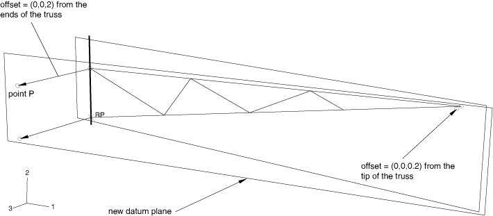
Create a datum plane using these three points. As before, the points
defining the plane should be chosen in a counterclockwise order.
Use the Create Wire: Planar tool to add a feature
to the part. Select the new datum plane as the sketch plane and the datum axis
created earlier as the edge that will appear vertical and on the left of the
sketch.
Note:
If the sketch plane is not oriented in the 1–2 plane, use the
Views toolbar
to change to the X–Y view.
Use the Add Sketch tool
 to retrieve the truss sketch. Translate the sketch by selecting
the vertex at the top left end of the new truss as the starting point of the
translation vector and the datum point labeled
P in
Figure 6
as the endpoint of the vector. Zoom in and rotate the view as necessary to
facilitate your selections.
Note:
If the points defining either the original or new
datum plane were not selected in a counterclockwise order, you will have to
mirror the sketch before translating it. If necessary, cancel the sketch
retrieval operation, create the necessary construction line for mirroring, and
retrieve the sketch again.
Click Done in the prompt area to exit the
Sketcher.

Create the cross brace geometry
Context:
Recall that the cross bracing must be treated as a separate part to properly
represent the pin joints between it and the trusses. The easiest way to sketch
the cross bracing, however, is to create wire features directly between the
locations of the joints in the trusses. Thus, we will adopt the following
method to create the cross bracing part: first, a copy of the truss part will
be created and the wires representing the cross brace will be added to it (we
cannot use this new part as is because the vertices at the joints are shared
and, thus, cannot represent a pin joint); then, we will use the cut feature
available in the
Assembly module
to perform a Boolean cut between the truss with the cross brace and the truss
without the cross brace, leaving the cross brace geometry as a distinct part.
The procedure is described in detail below.
In the
Model Tree,
click mouse button 3 on the Truss item underneath the
Parts container and select Copy from
the menu that appears. In the Part Copy dialog box, name
the new part Truss-all, and click
OK.
The pin locations are highlighted in
Figure 1.
Use the Create Wire: Point to Point tool
 . In the Create Wire Feature dialog box,
accept the default setting of Chained wires and click
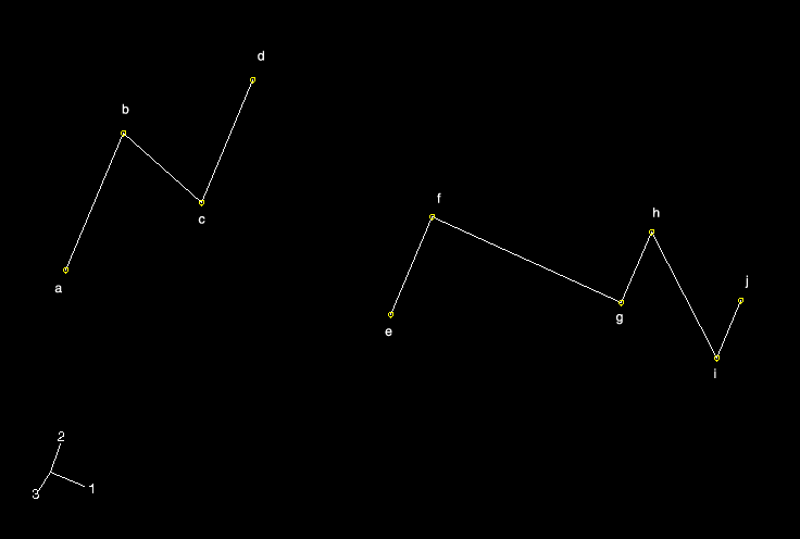
 to add the cross bracing geometry to the new part, as shown in
Figure 7
(the vertices in this figure correspond to those labeled in
Figure 1;
the visibility of the truss in
Figure 7
has been suppressed). Use the following coordinates to specify a similar view:
Viewpoint (1.19, 5.18, 7.89), Up
vector (−0.40, 0.76, −0.51).
Figure 7. Cross bracing geometry.
Create an instance of each part
(Truss and
Truss-all).
From the main menu bar of the
Assembly module,
select
.
In the Merge/Cut Instances dialog box, name the new part
Cross brace, select Cut
geometry in the Operations field, and click
Continue.
In the prompt area, click Instances. Select
Truss-all-1 as the instance to be cut.
Similarly, select Truss-1 as the instance that
will make the cut.
After the cut is made, a new part named Cross
brace is created that contains only the cross brace geometry.
The current model assembly contains only an instance of this part; the original
part instances are suppressed by default. Since we will need to use the
original truss in the model assembly, click mouse button 3 on
Truss-1 underneath the Instances
container and select Resume from the menu that appears to
resume this part instance.
We now define the beam section properties.
|

![]()
![]()
 , create two datum points at distances of (0, 1,
0) and (8, 1.5, 0.9) from the
reference point. These points represent points C and E, respectively, in
 in the
 , create a datum plane to serve as the sketch plane. Select the
reference point first, and then select the other two datum points in a
counterclockwise fashion. Click mouse button 2 to exit the procedure.
 , create a datum axis parallel to the
 to enter the Sketcher. Select the datum plane as the plane on
which to sketch the wire geometry; select the datum axis as the axis that will
appear vertical and to the left of the sketch. You may need to resize the view
to select these entities.
 , sketch the lines representing the main truss, as shown in


 , save the sketch as Truss.

 to retrieve the truss sketch. Translate the sketch by selecting
the vertex at the top left end of the new truss as the starting point of the
translation vector and the datum point labeled
P in
 . In the
  to add the cross bracing geometry to the new part, as shown in

 ; you cannot recover deleted features.