Creating the assembly | ||
| ||
Context:
Begin by creating a dependent instance of the floor (double-click Instances underneath the Assembly container).
The circuit board will be dropped at an angle; the final model assembly is shown in Figure 1.
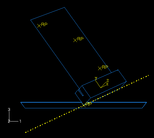
You will use the positioning tools in the Assembly module to position the packaging first; then you will position the board relative to the packaging. Finally, you will create a reference point at each datum point location of the board to represent the chips.
Position the packaging
From the main menu bar of the Assembly module, select ToolsDatum to create additional datum points that will help you position the packaging.
- Select Point as the type, and select Enter coordinates as the method.
- Create two datum points at (0, 0, 0) and (0.5, 0.707, 0.25).
- Click the auto-fit tool to see both points in the viewport.
In the Create Datum dialog box, select Axis as the type and 2 points as the method. Create a datum axis defined by the two datum points created in the previous step, selecting the point at (0.5, 0.707, 0.25) as the first point in the datum axis definition.
Tip: Use the Selection toolbar to restrict your selection to Datums. Instance the packaging.
Constrain the packaging so that the bottom edge aligns with the datum axis.
- From the main menu bar, select ConstraintEdge to Edge.
-
Select the edge of the packaging shown in
Figure 2
as a straight edge of the movable instance.
Tip: To obtain a better view of the model, select ViewSpecify from the main menu bar and select Viewpoint as the method; enter (−1, −1, 1) for the viewpoint vector and (0, 0, 1) for the up vector. Figure 2. Select a straight edge on the movable instance.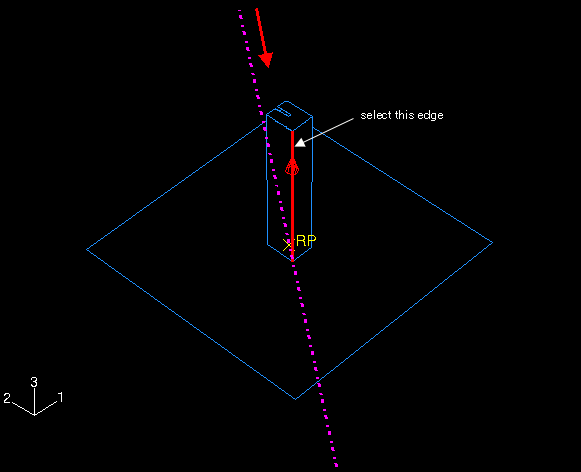
- Select the datum axis as the fixed instance.
-
If necessary, click Flip in the prompt area
to reverse the direction of the arrow on the packaging; click
OK when the arrows point in opposite directions as shown
in
Figure 2.
Tip: You may need to zoom out and rotate the model to see the arrow on the datum axis. The direction of this arrow depends on how you defined the axis initially; if the arrow on your axis points in the reverse direction of the one shown in the figure, the arrow on your packaging should also be opposite to the figure. Abaqus/CAE positions the packaging as shown in Figure 3.
Figure 3. Position 1: Constrain the bottom edge of the packaging to lie along the datum axis.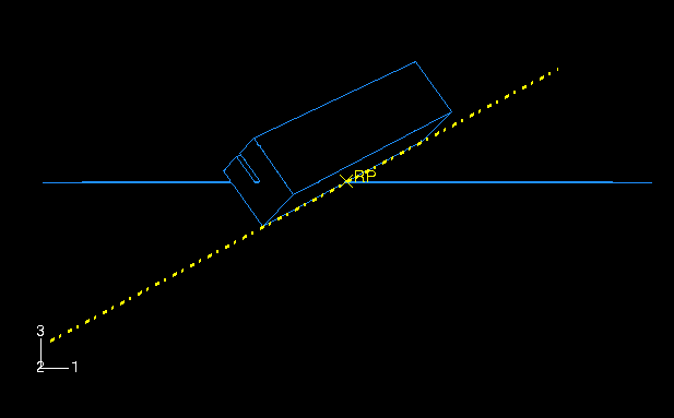
Note: Abaqus/CAE stores position constraints as features of the assembly; if you make a mistake while positioning the assembly, you can delete the position constraints. Simply click mouse button 3 on the constraint you wish to delete in the list of Position Constraints items found underneath the Assembly container in the Model Tree, and select Delete from the menu that appears.
Create a third datum point at (−0.5, 0.707, −0.5), and click the auto-fit tool again.
In the Create Datum dialog box, select Plane as the type and Line and point as the method. Create a datum plane defined by the datum axis created earlier and the datum point created in the previous step.
Constrain the packaging so that the bottom face lies on the datum plane.
- From the main menu bar, select ConstraintFace to Face.
-
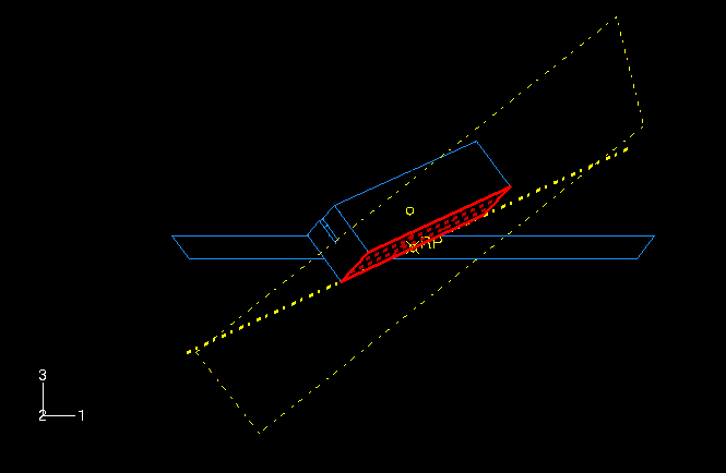
Select the face of the packaging shown in
Figure 4
as a face of the movable instance.
Figure 4. Select a face on the movable instance.
- Select the datum plane as the fixed instance.
- If necessary, click Flip in the prompt area; click OK when both arrows point in the same direction.
- Accept the default distance of 0.0 from the fixed plane.
Finally, constrain the packaging to contact the floor at its center.
- From the main menu bar, select ConstraintCoincident Point.
-
Select the lowest vertex of the packaging as a point on the
movable instance, and select the reference point on the floor as a point on the
fixed instance.
Abaqus/CAE positions the packaging as shown in Figure 5.
Figure 5. Final position of the packaging relative to the floor.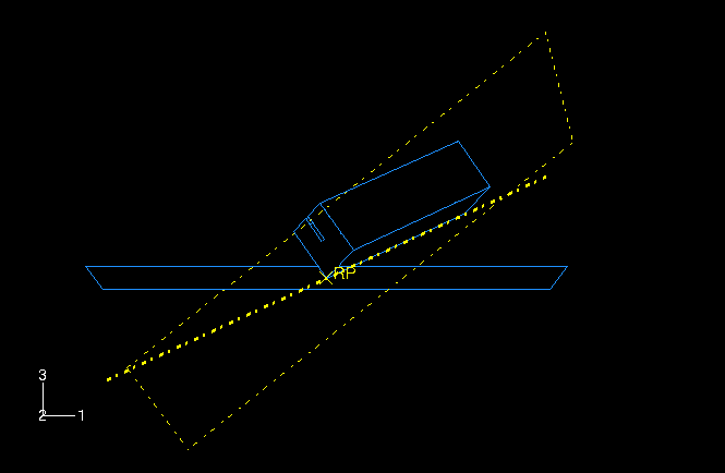
Now, translate the floor slightly downward to ensure that there is no initial overclosure between the packaging and the floor.
- Convert the relative position constraints to absolute constraints to avoid conflicts. From the main menu bar, select InstanceConvert Constraints. Select the packaging in the viewport, and click Done in the prompt area.
- From the main menu bar, select InstanceTranslate.
- Select the floor in the viewport.
- Enter (0.0, 0.0, 0.0) as the start point for the translation vector and (0.0, 0.0, −0.0001) as the end point for the translation vector.
- Click OK to accept the new position.
![]()
Position the circuit board
Instance the circuit board. In the Create Instance dialog box, toggle on Auto-offset from other instances.
From the main menu bar, select ConstraintParallel Face. Select the face of the board as a face on the movable instance; select a face on the long side of the packaging as a face on the fixed instance. If necessary, click Flip in the prompt area to ensure that the arrows on both faces point in the directions shown in Figure 6; click OK to complete the constraint.
Figure 6. Parallel face constraint for the circuit board.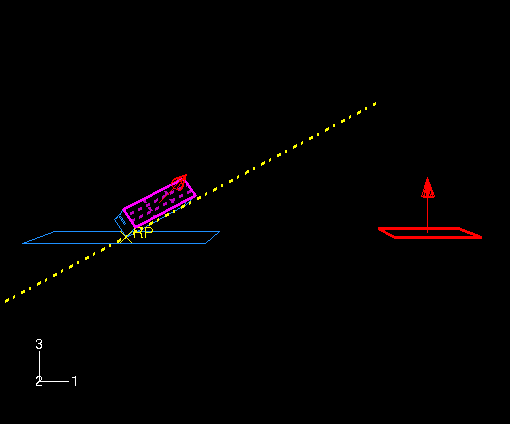
From the main menu bar, select ConstraintParallel Edge. Select the top edge of the board as an edge on the movable instance. Select an edge along the length of the packaging as an edge on the fixed instance. If necessary, click Flip in the prompt area to ensure that the arrows on both edges point in the same direction, as shown in Figure 7; click OK to complete the constraint.
Figure 7. Parallel edge constraint for the circuit board.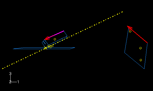
From the main menu bar, select ConstraintCoincident Point. Select the midpoint of the bottom of the board as a point on the movable instance. Select the datum point at the center of the cut in the packaging as a point on the fixed instance.
Tip: Use the Selection toolbar to restrict your selection to Datums. Figure 8 shows the final position of the circuit board. The circuit board and the slot in the packaging are the same thickness (2 mm) so there is a snug fit between the two bodies.
Figure 8. Final position of the circuit board.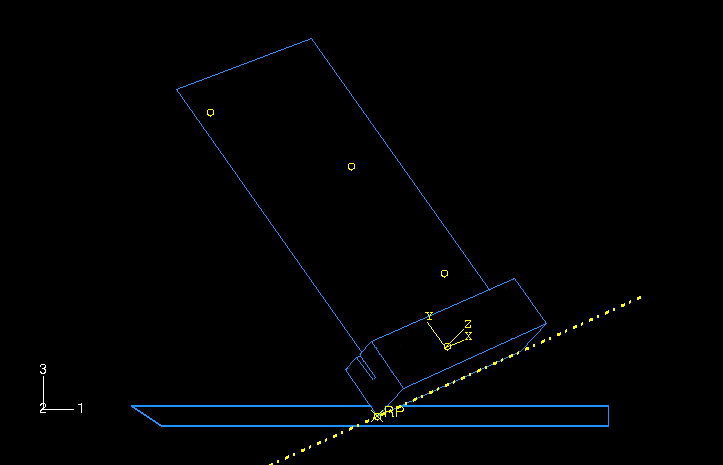
![]()
Create the chips
Create a reference point at each of the three datum point locations on the board to represent each chip. Each of these reference points will later be assigned mass properties. To create a reference point, select ToolsReference Point from the main menu bar of the Assembly module.
Once you have created the reference points, the assembly is complete.
Before continuing, create the following geometry sets that you will use to specify output requests and mass properties:
-
TopChip for the reference point of the top chip
-
MidChip for the reference point of the middle chip
-
BotChip for the reference point of the bottom chip
-
BotBoard for the bottom edge of the board
-