Context:
In this example you will move the solid hinge piece while the hinge piece with the lubrication hole will remain fixed. You will apply three types of position constraints to position the two hinge pieces correctly.
First, constrain the solid hinge piece so that the two flanges face each other. From the main menu bar, select .
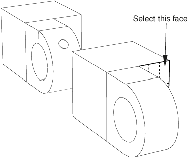
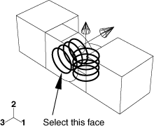
From the movable part instance, select the face of the solid hinge piece shown in Figure 1.
Figure 1. Select a face on the movable part instance.
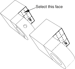
From the fixed part instance, select the face of the hinge piece with the lubrication hole shown in Figure 2. Abaqus/CAE highlights the face on the movable part instance in red and the face on the fixed part instance in magenta.
Figure 2. Select a face on the fixed instance.
Abaqus/CAE displays red arrows on each selected face; the movable instance will be positioned so that the arrows point in the same direction. You can change the direction of the arrow on the movable instance if necessary.
From the prompt area, click Flip to change the direction of the arrow. Click OK when the arrows point toward each other.
In the text box that appears in the prompt area, type the clearance (0.04) that will remain between the two parts, as measured along the normal to the selected face of the fixed part, and press Enter.
Abaqus/CAE rotates the solid hinge piece so that the two selected faces are parallel to each other and 0.04 meters apart, as shown in Figure 3.
Figure 3. Position 1: Constrain the flange of the solid hinge piece to face the flange of the hinge piece with the lubrication hole.
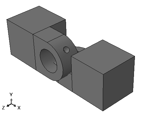
The two pieces overlap because the position of the solid hinge piece is not fully determined by the position constraint you have applied. You will need to apply two more position constraints to obtain the desired position.
Next, align the two flange holes. From the main menu bar, select .
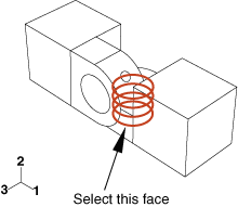
Select the flange hole on the solid hinge piece, as shown in Figure 4. (You may find it helpful to display the wireframe view of the two pieces.)
Figure 4. Select a cylindrical face on the movable instance.
Select the flange hole on the hinge piece with the lubrication hole, as shown in Figure 5.
Abaqus/CAE displays red arrows on each selected face.
Figure 5. Select a cylindrical face on the fixed instance.
From the prompt area, click Flip to change the direction of the arrow on the movable part instance. Click OK when the arrow points downward.
Abaqus/CAE positions the two hinge pieces so that the two flange holes are coaxial.
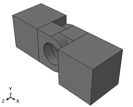
Use the rotate tool  to look at the top view of the two pieces. Notice that the two flanges are now overlapping, as shown in Figure 6.
Figure 6. Position 2: Constrain the two flange holes to lie along the same axis.
Finally, add a constraint to eliminate the overlap between the two flanges. From the main menu bar, select .
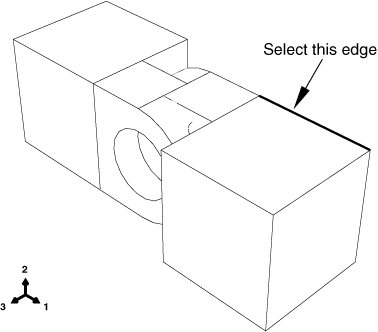
Select the straight edge on the solid hinge piece shown in Figure 7.
Figure 7. Select a straight edge on the movable instance.
Select the corresponding edge of the hinge piece with the lubrication hole, as shown in Figure 8.
Figure 8. Select a straight edge on the fixed instance.
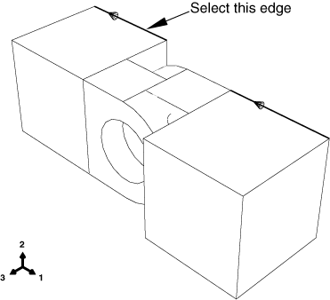
Abaqus/CAE displays red arrows on each selected face.
If necessary, flip the arrows so they point in the same direction; then click OK to apply the constraint.
Abaqus/CAE positions the two hinge pieces so that the two selected edges are colinear, as shown in Figure 9.
Figure 9. Final position: Constrain an edge of each hinge piece to lie along the same line.
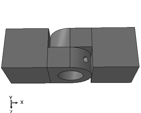


 to look at the top view of the two pieces. Notice that the two flanges are now overlapping, as shown in


