Creating and positioning an instance of the pin | ||
| ||
In the Model Tree, double-click Instances underneath the Assembly container.
In the Create Instance dialog box, toggle off Auto-offset from other instances and create an instance of the pin.
Constrain the pin to lie along the same axis as the two flange holes. Use the ConstraintCoaxial menu as you did when you aligned the two flange holes in the previous section. (You can select either of the flange holes as the cylindrical surface of the fixed instance, and the direction of the arrows is not important.)
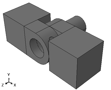
Abaqus/CAE will position the pin as shown in Figure 1.
Figure 1. Align the pin to be coaxial with the two flange holes.
From the main menu bar, select ToolsQuery.
The Query dialog box appears.
Select Distance from the list of General Queries.
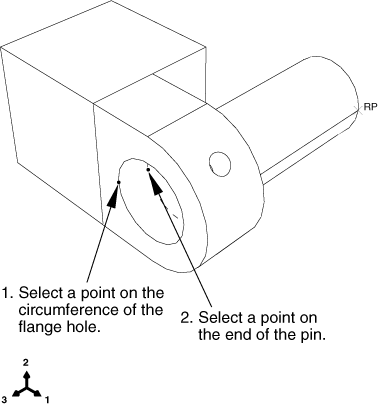
The Distance query allows you measure the X-, Y-, and Z-components of the vector connecting two selected points. You need to determine the distance between the end of the pin and the hinge containing the lubrication hole; the two points to select are illustrated in Figure 2.
Figure 2. Determining the position of the pin.
- To define one end of the vector, select a point on the circumference of the hole in the flange containing the lubrication hole.
- To define the other end of the vector, select the vertex on the pin that is inside the hinge containing the lubrication hole.
Abaqus/CAE displays the vector distance between the two selected points along with the X-, Y-, and Z-components of the vector in the message area. You will translate the pin along the Z-axis; the Z-component of the distance is 0.01 meters. You want to position the pin symmetrically between the hinges, so you will translate it 0.02 meters.
From the main menu bar, select InstanceTranslate.
Select the pin as the part instance to move, and click Done to indicate that you have finished selecting instances to move.
In the text boxes in the prompt area, enter a start point for the translation vector of 0,0,0 and an end point of 0,0,0.02.
Abaqus/CAE translates the pin a distance of 0.02 along the Z-axis and displays a temporary image of the new position of the pin.
Note:
If the position of a temporary image (colored red) is not correct, you can use the buttons in the prompt area to correct the problem. Click either the Cancel button (
 ) to cancel the procedure or the Previous button (
 ) to step back through the procedure.
From the prompt area, click OK.
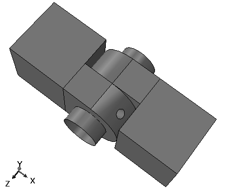
The finished assembly is shown in Figure 3.
Figure 3. Shaded view of the finished assembly.
Before proceeding, convert all position constraints to absolute positions. From the main menu bar, select InstanceConvert Constraints. Select all part instances, and click Done in the prompt area.