Context:
In this model the bottom-left portion of the frame is constrained completely
and, thus, cannot move in any direction. The bottom-right portion of the frame,
however, is fixed in the vertical direction but is free to move in the
horizontal direction. The directions in which motion is possible are called
degrees of freedom (dof).
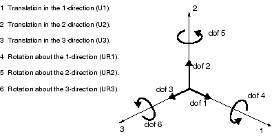
The labeling convention used for the displacement and rotational degrees of
freedom in
Abaqus
is shown in
Figure 1.
Figure 1. Displacement and rotational degrees of freedom.

In this example all the constraints are in the global 1- or 2-directions. In
many cases constraints are required in directions that are not aligned with the
global directions. In such cases you can define a local coordinate system for
boundary condition application. The skew plate example in
Using Shell Elements
demonstrates how to do this.
In the
Model Tree,
double-click the BCs container.
Abaqus/CAE
switches to the
Load module,
and the Create Boundary Condition dialog box appears.
In the Create Boundary Condition dialog box:
-
Name the boundary condition Fixed.
-
From the list of steps, select
Initial as the step in which the boundary
condition will be activated. All the mechanical boundary conditions specified
in the Initial step must have zero magnitudes.
This condition is enforced automatically by
Abaqus/CAE.
-
In the Category list, accept
Mechanical as the default category selection.
-
In the Types for Selected Step list, select
Displacement/Rotation, and click
Continue.
Abaqus/CAE
displays prompts in the prompt area to guide you through the procedure. For
example, you are asked to select the region to which the boundary condition
will be applied.
To apply a prescribed condition to a region, you can either
select the region directly in the viewport or apply the condition to an
existing set (a set is a named region of a model). Sets are a convenient tool
that can be used to manage large complicated models. In this simple model you
will not make use of sets.
In the viewport, select the vertex at the bottom-left corner of the
frame as the region to which the boundary condition will be applied. Name the
associated set left.
Click mouse button 2 in the viewport or click
Done in the prompt area to indicate that you have
finished selecting regions.
The Edit Boundary Condition dialog box appears.
When you are defining a boundary condition in the initial step, all available
degrees of freedom are unconstrained by default.
In the dialog box:
-
Toggle on U1 and U2
since all translational degrees of freedom need to be constrained.
-
Click OK to create the boundary condition
and to close the dialog box.
Abaqus/CAE
displays two arrowheads at the vertex to indicate the constrained degrees of
freedom.
Repeat the above procedure to constrain degree of freedom
U2 at the vertex at the bottom-right corner of the frame.
Name this boundary condition Roller and the
associated set right.
In the
Model Tree,
click mouse button 3 on the BCs container and select
Manager from the menu that appears.
Abaqus/CAE
displays the Boundary Condition Manager. The manager
indicates that the boundary conditions are
Created (activated) in the initial step and
are Propagated from base state (continue to be
active) in the analysis step Apply load.
Click Dismiss to close the Boundary
Condition Manager.
