Reference surface offsets | ||
| ||
Shell offsets can also be used to define a more precise surface geometry for contact problems where shell thickness is important. Another situation where the offset from the midsurface may be important is when a shell with continuously varying thickness is modeled. In this case defining the nodes at the shell midplane can be difficult. If one surface is smooth while the other is rough, as in some aircraft structures, it is easiest to use shell offsets to define the nodes at the smooth surface.
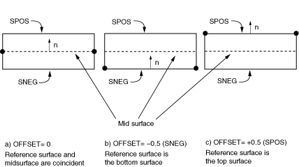
Offsets can be introduced by specifying an offset value, which is defined as the distance (measured as a fraction of the shell's thickness) from the shell's midsurface to the reference surface containing the element's nodes. Positive values of the offset are in the positive normal direction. When the offset is set equal to 0.5 or SPOS, the top surface of the shell is the reference surface. When the offset is set equal to –0.5 or SNEG, the bottom surface is the reference surface. The default offset is 0, which indicates that the middle surface of the shell is the reference surface. These three reference surface offset settings are shown in Figure 1 for a mesh where the nodal positions are adjusted to keep the position of the midsurface constant.

The degrees of freedom for the shell are associated with the reference surface. The element's area and all kinematic quantities are calculated there. Large offset values for curved shells may lead to a surface integration error, affecting the stiffness, mass, and rotary inertia for the shell section. For stability purposes Abaqus/Explicit also automatically augments the rotary inertia used for shell elements on the order of the offset squared, which may result in errors in the dynamics for large offsets. When large offsets from the shell's midsurface are necessary, use multi-point constraints or rigid body constraints instead.