Creating assembly-level sets | ||
| ||
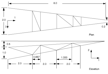
Since the parts are already aligned with the global Cartesian coordinate system shown in Figure 1, no further manipulations of the parts are necessary.

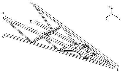
At this point, however, it is convenient to define assembly-level geometry sets that will be used later. In the Model Tree, expand the Assembly container and double-click Sets. Define a geometry set containing the vertices corresponding to points A through D (refer to Figure 2 for the exact locations), and name the set Attach. When defining this set, be sure to select the vertices of the truss and not reference points. You may need to use the Selection toolbar to aid in your selection.

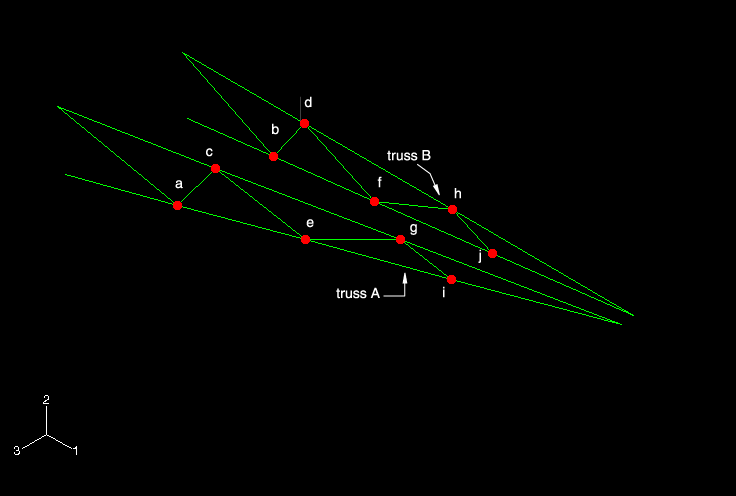
In addition, create sets at the vertices located at the tips of the trusses (location E in Figure 2). Name the sets Tip-a and Tip-b, with Tip-a being the geometry set associated with truss A (see Figure 3). Finally, create a set for each region where beam normals will be specified, referring to Figure 3. For truss A, create a set named Inner-a for the region indicated by R2 and a set named Leg-a for the region indicated by R5; create corresponding sets Inner-b and Leg-b for truss B.
