Cross-section orientation | ||
| ||

The -direction is always (0.0, 0.0, −1.0) for two-dimensional beam elements.
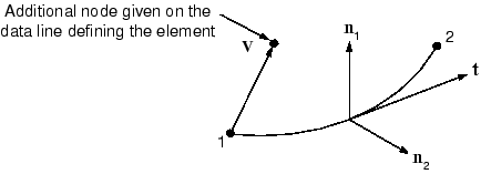
For three-dimensional beam elements there are several ways to define the orientation of the local beam section axes. The first is to specify an extra node on the data line defining the element (this method requires manually editing the input file created by Abaqus/CAE). The vector, , from the first node in the beam element to this additional node (see Figure 1), is used initially as an approximate -direction. Abaqus then defines the beam's -direction as . Having determined , Abaqus defines the actual -direction as . This procedure ensures that the local tangent and local beam section axes form an orthogonal system.
Alternatively, you can give an approximate -direction when you define the beam section properties in Abaqus/CAE. Abaqus then uses the procedure described above to calculate the actual beam section axes. If you specify both an extra node and an approximate -direction, the additional node method takes precedence. Abaqus uses the vector from the origin to the point (0.0, 0.0, −1.0) as the default -direction if you provide no approximate -direction.
There are two methods that can be used to override the -direction defined by Abaqus; both require editing the input file manually. One is to give the components of as the 4th, 5th, and 6th data values following the nodal coordinates. The alternative is to specify the normal direction directly with the NORMAL option (this option can be added using the Abaqus/CAE Keywords Editor). If both methods are used, the latter takes precedence. Abaqus again defines the -direction as .
The -direction that you provide need not be orthogonal to the beam element tangent, . When you provide the -direction, the local beam element tangent is redefined as the value of the cross product . It is quite possible in this situation that the redefined local beam tangent, , will not align with the beam axis, as defined by the vector from the first to the second node. If the -direction subtends an angle greater than 20° with the plane perpendicular to the element axis, Abaqus issues a warning message in the data file.
The example presented in Example: cargo crane explains how to assign the beam cross-section orientation using Abaqus/CAE.