Stretching of a thin sheet with a hemispherical punch | ||
| ||
ProductsAbaqus/StandardAbaqus/Explicit
Stamping of sheet metals by means of rigid punches and dies is a standard manufacturing process. In most bulk forming processes the loads required for the forming operation are often the primary concern. However, in sheet forming the prediction of strain distributions and limit strains (which define the onset of local necking) are most important. Such analysis is complicated in that it requires consideration of large plastic strains during deformation, an accurate description of material response including strain hardening, the treatment of a moving boundary that separates the region in contact with the punch head from the unsupported one, and the inclusion of friction between the sheet and the punch head.
Geometry and model
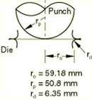
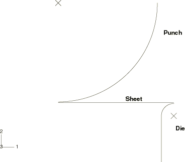
The geometry of this problem is shown in Figure 1. The sheet being stretched has a clamping radius, , of 59.18 mm. The radius of the punch, , is 50.8 mm; the die radius, , is 6.35 mm; and the initial thickness of the sheet, , is 0.85 mm. Such a sheet has been tested experimentally by Ghosh and Hecker (1975) and has been analyzed by Wang and Budiansky (1978) using an axisymmetric membrane shell finite element formulation. The analysis is conducted statically in Abaqus/Standard and dynamically in Abaqus/Explicit such that inertial forces are relatively small. The initial configuration for the analysis is shown in Figure 2.
The sheet, the punch, and the die are modeled as separate parts, each instanced once. As an axisymmetric problem in Abaqus/Standard the sheet is modeled using 50 elements of type SAX1 (or MAX1) or 25 elements of type SAX2 (or MAX2). The Abaqus/Explicit model uses 50 elements of type SAX1. Mesh convergence studies (not reported here) have been done and indicate that these meshes give acceptably accurate results for most of the values of interest. To test the three-dimensional membrane and shell elements in Abaqus/Standard, a 10° sector is modeled using 100 elements of type S4R, S4, SC8R, or M3D4R or 25 elements of type M3D9R. All these meshes are reasonably fine; they are used to obtain good resolution of the moving contact between the sheet and the dies. In the Abaqus/Standard shell models nine integration points are used through the thickness of the sheet to ensure the development of yielding and elastic-plastic bending response; in Abaqus/Explicit five integration points are used through the thickness of the sheet.
The rigid punch and die are modeled in Abaqus/Standard as analytical rigid surfaces with a surface in conjunction with a rigid body constraint. The top and bottom surfaces of the sheet are defined with surface definitions. In Abaqus/Explicit the punch and die are modeled as rigid bodies; the surface of the punch and die are modeled either by analytical rigid surfaces or RAX2 elements. In the Abaqus/Explicit analyses the rigid surfaces are offset from the blank by half the thickness of the blank because the contact algorithm in Abaqus/Explicit takes the shell thickness into account. Similarly, when the surface-to-surface contact formulation in Abaqus/Standard is used, the blank thickness is considered by default and the rigid surfaces are offset from the blank by half the blank thickness, consistent with the physical reality. However, most of the input files presented in this section use the node-to-surface contact formulation in Abaqus/Standard. In these cases the shell thickness is ignored, and the mid-surface of the shell is used in the contact calculations as an approximation.
![]()
Material properties
The material (aluminum-killed steel) is assumed to satisfy the Ramberg-Osgood relation between true stress and logarithmic strain,
where Young's modulus, E, is 206.8 GPa; the reference stress value, K, is 0.510 GPa; and the work-hardening exponent, n, is 4.76. In the present Abaqus analyses the Ramberg-Osgood relation is approximated using an elastic-plastic material. The material is assumed to be linear elastic up to a yield stress of 170.0 MPa, and the stress-strain curve beyond the yield stress is defined in piecewise linear segments. Poisson's ratio is 0.3.
The membrane element models in Abaqus/Standard are inherently unstable in a static analysis unless some prestress is present in the elements prior to the application of external loading. Therefore, an equibiaxial initial stress condition equal to 5% of the initial yield stress is prescribed for the membrane elements in Abaqus/Standard.
![]()
Contact interactions
The contact between the sheet and the rigid punch and the rigid die is modeled with a contact pair. The mechanical interaction between the contact surfaces is assumed to be frictional contact, with a coefficient of friction of 0.275.
![]()
Loading
The Abaqus/Standard analysis is carried out in five steps; the Abaqus/Explicit analysis is carried out in four steps. In Abaqus/Explicit the velocity of the punch head is prescribed using a velocity boundary condition whose amplitude is ramped up to 30 m/s at 1.24 milliseconds during the first step and then kept constant until time reaches 1.57 milliseconds at the end of the second step. It is then ramped down to zero at a time of 1.97 milliseconds at the end of the third step. In the first three steps of the Abaqus/Standard and Abaqus/Explicit analyses, the punch head is moved toward the sheet through total distances of 18.6 mm, 28.5 mm, and 34.5 mm, respectively. The purpose of these three steps is to compare the results with those provided experimentally by Ghosh and Hecker for these punch displacements. More typically the punch would be moved through its entire travel in one step.
Two final steps are included in the Abaqus/Standard analysis. In the first step the metal sheet is held in place and the contact pairs are removed from the model. In the second step the original boundary conditions for the metal sheet are reintroduced for springback analysis. However, this springback step is not included for the analyses using membrane elements, since these elements do not have any bending stiffness and residual bending stress is often a key determinant of springback.
In the final step of the Abaqus/Explicit analysis the punch head is moved away from the sheet for springback analysis. A viscous pressure load is applied to the surface of the shell during this step to damp out transient wave effects so that quasi-static equilibrium can be reached quickly. This effect happens within approximately 2 milliseconds from the start of unloading. The coefficient of viscous pressure is chosen to be 0.35 MPa sec/m, approximately 1% of the value of , where is the material density of the sheet and is the dilatational wave speed. A value of viscous pressure of would absorb all the energy in a pressure wave. For typical structural problems choosing a small percentage of this value provides an effective way of minimizing ongoing dynamic effects. Static equilibrium is reached when residual stresses in the sheet are reasonably constant over time.
![]()
Results and discussion
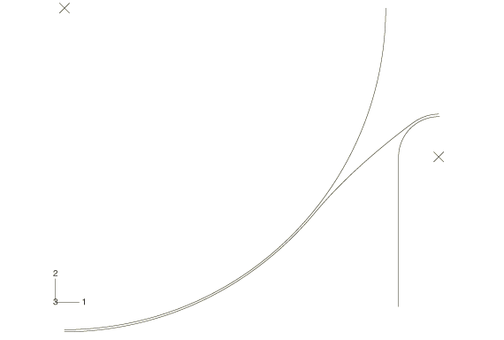
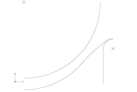
Figure 2 shows the initial, undeformed profile of the blank, the die, and the punch. Figure 3 illustrates the deformed sheet and the punch and the die. Figure 4 shows a plot of the same system after the punch is lifted back, showing the springback of the sheet.
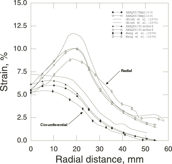
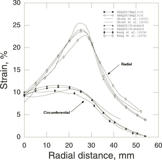
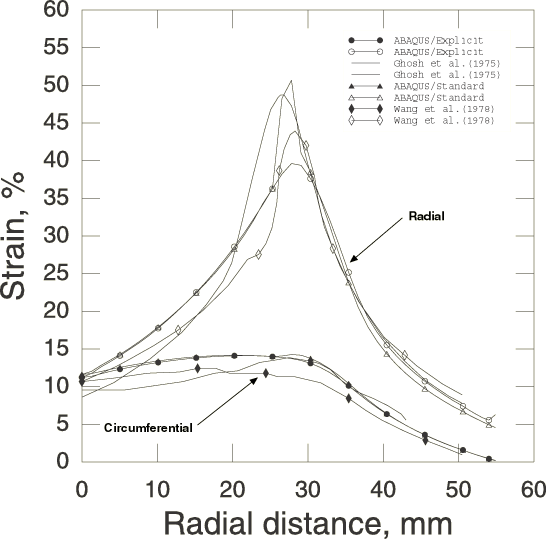
Figure 5 shows the distribution of nominal values of radial and circumferential membrane strain in the sheet for an 18.6 mm punch head displacement. Figure 6 shows the strain distributions at a punch head displacement of 28.5 mm, and Figure 7 shows the strain distributions at a punch head displacement of 34.5 mm. The strain distributions for the SAX1 models compare well with those obtained experimentally by Ghosh and Hecker (1975) and those obtained numerically by Wang and Budiansky (1978), who used a membrane shell finite element formulation. The important phenomenon of necking during stretching is reproduced at nearly the same location, although slightly different strain values are obtained. Draw beads are used to hold the edge of the sheet in the experiment, but in this analysis the sheet is simply clamped at its edge. Incorporation of the draw bead boundary conditions may further improve the correlation with the experimental data.
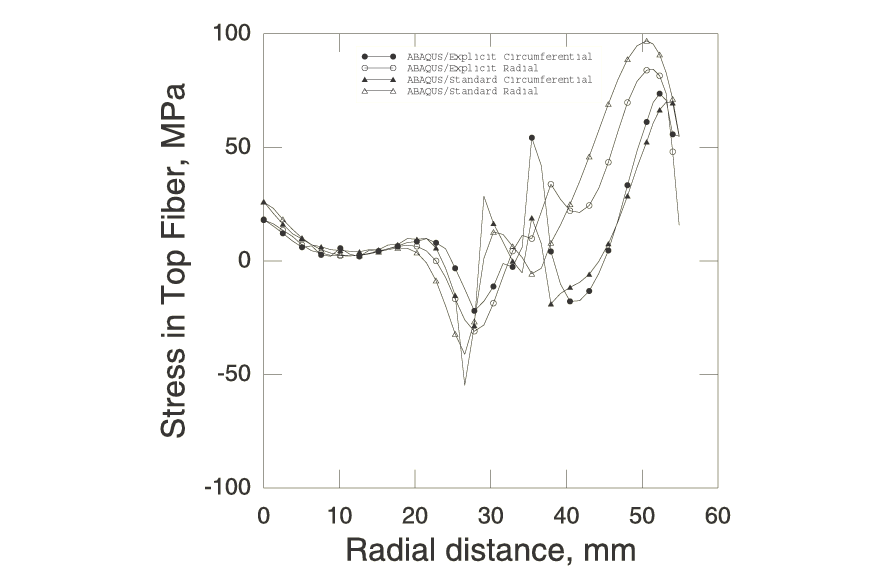
A spike can be observed in the radial strain distribution toward the edge of the sheet in some of the Abaqus/Standard shell models. This strain spike is the result of the sheet bending around the die. The spike is not present in the membrane element models since they possess no bending stiffness. All of the Abaqus/Standard results presented in Figure 5 through Figure 9 use the node-to-surface contact formulation. Similar results are obtained when using the surface-to-surface contact formulation.
The results obtained with the axisymmetric membrane models are compared with those obtained from the axisymmetric shell models and are found to be in good agreement.
These analyses assume a value of 0.275 for the coefficient of friction. Ghosh and Hecker do not give a value for their experiments, but Wang and Budiansky assume a value of 0.17. The coefficient of friction has a marked effect on the peak strain during necking and may be a factor contributing to the discrepancy of peak strain results during necking. The values used in these analyses have been chosen to provide good correlation with the experimental data.
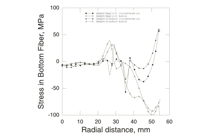
The distributions of the residual stresses on springback of the sheet are shown in Figure 8 and Figure 9.
![]()
Input files
Abaqus/Standard input files
- thinsheetstretching_m3d4r.inp
-
Element type M3D4R.
- thinsheetstretching_m3d4r_surf.inp
-
Element type M3D4R using surface-to-surface contact while accounting for shell thickness.
- thinsheetstretching_m3d9r.inp
-
Element type M3D9R.
- thinsheetstretching_max1.inp
-
Element type MAX1.
- thinsheetstretching_max2.inp
-
Element type MAX2.
- thinsheetstretching_s4.inp
-
Element type S4.
- thinsheetstretching_s4r.inp
-
Element type S4R.
- thinsheetstretching_s4r_po.inp
-
POST OUTPUT analysis.
- thinsheetstretching_sc8r.inp
-
Element type SC8R.
- thinsheetstretching_sax1.inp
-
Element type SAX1.
- thinsheetstretching_sax2.inp
-
Element type SAX2.
- thinsheetstretching_restart.inp
-
Restart of thinsheetstretching_sax2.inp.
Abaqus/Explicit input files
- hemipunch_anl.inp
-
Model using analytical rigid surfaces to describe the rigid surface.
- hemipunch.inp
-
Model using rigid elements to describe the rigid surface.
![]()
References
- “Failure in Thin Sheets Stretched Over Rigid Punches,” Metallurgical Transactions, vol. 6A, pp. 1065–1074, 1975.
- “Analysis of Sheet Metal Stamping by a Finite Element Method,” Journal of Applied Mechanics, vol. 45, pp. 73–82, 1978.
![]()
Figures
