Pressurized fuel tank with variable shell thickness | ||
| ||
ProductsAbaqus/Standard
Geometry and model
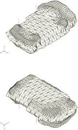
The mesh shown in Figure 1 is used in this example to model a fuel tank and its support straps. The mesh uses 2812 3-node shell elements (S3R), with the support straps modeled with 32 2-node beam elements (B31). Depending on the desired accuracy and detail of the solution, the analyst may identify some regions of the mesh in which additional refinement, or second-order elements, would be appropriate. The fuel tank would fit within a box of dimensions 450 mm × 200 mm × 680 mm. An internal pressure of 7 × 10⁻³ MPa is applied statically to the tank.
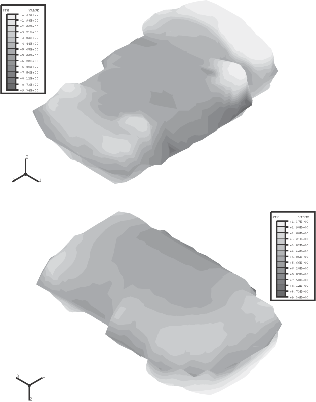
Analyses are conducted for a uniform shell thickness of 5 mm and for a spatially varying shell thickness in the range 1.38 mm to 9.35 mm (see Figure 2), which is a more accurate representation of the tank. The uniform thickness analysis provides a comparison to judge the effects of variable thickness. The overall volume of plastic modeled in the variable thickness analysis is about 93% of that in the uniform thickness analysis. For the variable thickness analysis the shell cross-section indicates that the shell thickness is to be interpolated from nodal values specified with nodal thickness. For elements with more than one integration point, this approach results in a thickness that can vary over the element.
The materials are modeled as isotropic elastic. The plastic fuel tank has a Young's modulus of 0.6 GPa and a Poisson's ratio of 0.3. The steel support straps have a Young's modulus of 206.8 GPa and a Poisson's ratio of 0.29. Geometrically nonlinear effects are significant in this example, so geometric nonlinearity is included in the step.
![]()
Results and discussion
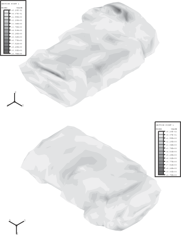
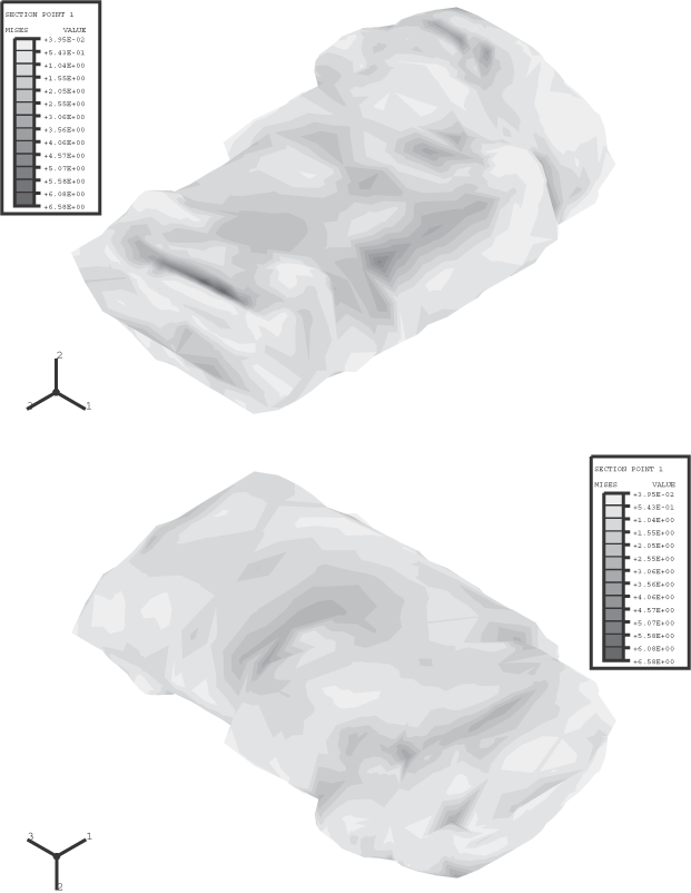
Contour plots of the Mises stress at the inner surface of the fuel tank (section point 1 in the shell elements) for the variable shell thickness and uniform shell thickness analyses are shown in Figure 3 and Figure 4. The ratio of the maximum Mises stress found in the variable thickness analysis to that found in the uniform thickness analysis is 1.5. For the variable thickness analysis, the maximum Mises stress occurs at a location where the fuel tank skin is relatively thin (see Figure 2 and Figure 3).
Examination of the y-component of displacement shows that the overall expansion of the tank in the y-direction is about 1.5% greater in the variable thickness analysis.
![]()
Input files
- pressfueltank_variablethick.inp
-
Example using variable shell thickness.
- pressfueltank_uniformthick.inp
-
Example using uniform shell thickness.
- pressfueltank_node.inp
-
Nodal coordinate data for both models.
- pressfueltank_shellelement.inp
-
Shell element connectivity data for both models.
- pressfueltank_beamelement.inp
-
Beam element connectivity data for both models.
- pressfueltank_shellthickness.inp
-
Shell thickness data for the variable shell thickness model.
![]()
References
- Plastic Processing Department, Rue de Ransbeek, 310, B-1120 Brussels, Belgium.
![]()
Figures


