Context:
Abaqus/CAE
closes the space between two sets of connected edges with new faces. You can
choose whether to make the new faces tangent to the selected edges, connect the
edges using the shortest path between them, or specify a path that the new
faces must follow between the selected edges.
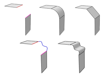
Figure 1
shows two faces with the selected edges highlighted. In this example, the
tangent method creates a face with a smooth radius tangent to both original
faces, the shortest path method creates a planar face, and the selected path
method creates a face with the profile of the selected wire edge.
Figure 1. Creating blended faces using the tangent, shortest path, and specify
path methods.

You can also create a blended face to join edges and faces.
Abaqus/CAE
creates blended faces between the selected edges and faces using the shortest
path method. When you create a blended face feature between edges and an
existing face, the new faces are always perpendicular to the existing face. The
free edges are extended or shortened as needed to intersect with the edges of
the face.
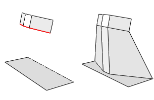
Figure 2
shows the selected edges and the feature created by blending between them and a
planar face. The ends of the center edge are a perpendicular projection from
the planar face, and the outer ends of the left and right edges are extended to
meet the edges of the planar face.
Figure 2. Creating a blended face between edges and a face.

The blend operation is stored as a feature of the part; therefore, you can
use the
Model Tree
to delete faces that you created.
From the main menu bar, select
.
Abaqus/CAE
displays the Geometry Edit dialog box.
From the dialog box, select the Face category and
the Blend method.
Select edges for the first side of the blended face.
You can select edges individually or by edge angle. For more
information on selecting objects in the viewport, see
Selecting objects within the current viewport.
You can also select an existing set of edges.
Note:
The default selection method is based on the selection method you
most recently employed. To revert to the other method, click Select
in Viewport or Sets on the right side of the
prompt area.
From the prompt area, click Done.
Select edges or faces for the second side of the blended face.
If you select faces for the second side, the edges selected in Step 3
must have a perpendicular projection onto the faces or
Abaqus/CAE
will not be able to create a blended face for the selections.
From the prompt area, click Done to complete
your selection and to open the Blend Faces dialog box.
Choose one of the available blend methods:
- Tangent
-
Abaqus/CAE
will create blended faces tangent to the faces containing the first and second
side edges. To use this method, the edges selected in Step 3 and Step 4 must be
free edges—edges that belong to only one feature face—so that
Abaqus/CAE
can calculate tangency.
- Shortest
path
-
Abaqus/CAE
will create blended faces that connect the first and second side edges using
the shortest path between them. If you selected a face or faces for the second
side of the blend, this is the only blend method available.
- Specify
path
-
Specify a path between the edges. Click Select
to choose an existing edge or wire feature that joins the end of one of the
first side edges to the end of one of the second side edges.
Abaqus/CAE
will create blended faces using the profile of the selected path.
Click Preview to preview the blended face that
would result from the current selections.
Click OK.
Abaqus/CAE
creates the blended face feature. The blend procedure restarts at Step 3 using
the most recently used selection method.
To exit the blend procedure, either
-
click the cancel button
 in the prompt area, or
-
click mouse button 2 anywhere in the
Abaqus/CAE
window, or
-
select another operation from the
Geometry Edit toolset
or from the tools in the
Part module.


 tool, located with the edit tools in the
 in the prompt area, or