Using the limiting angle, layer, and analytic methods to select multiple element faces | ||||||
|
| |||||

The angle selection method is described in Using the angle and feature edge method to select multiple objects. The limiting angle, layer, and analytic methods are available only while selecting orphan element faces to create new geometric faces.
- By limiting angle
-
Selecting objects using a limiting angle is a two-step process:
-
In the prompt area, you enter an angle (from 0° to 90°).
-
From the part or assembly, you select an orphan element face.
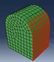
The angle must be greater than the total angle between the selected element face and the element faces connected to it. Abaqus/CAE starts from the selected geometry and selects all adjacent geometry until the angle between the selected face and the last face in the series of adjacent faces meets or exceeds the angle you entered. Figure 2 shows selection of element faces with a limiting angle of 45°, and one of the vertical element faces below the rounded area is picked.
Figure 2. A limiting angle of 45° with a selected vertical face.
Increasing the limiting angle to its maximum of 90° would select the faces up to the top of the rounded section. In contrast, using the angle method with an angle of 13° or more would continue the selection around the rounded portion and down the far side since the angle between each adjacent face is less than 13°.
-
- By layer
-
Selecting objects using the layer method is a two-step process:
-
In the prompt area, you enter a number of layers.
-
From the part or assembly, you select an orphan element face.
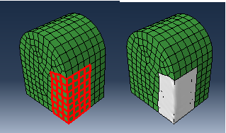
Abaqus/CAE starts from the selected face and selects layers of adjacent element faces around it in all directions. Selection continues around corners and other features until the number of layers is reached or until there are no more adjacent orphan element faces.
Figure 3 illustrates the selection of three layers of orphan shell element faces around a starting face and the resulting geometric face.
Figure 3. Face layer selection and creation of a geometric face.
As shown in Figure 3, layer selection can traverse sharp corners and other model features that would normally signify the end of a geometric face. In most cases you should preserve logical model edges and other features by creating separate faces. Otherwise, the resulting geometry may be difficult to repair and mesh.
Note:
When you are working with solid orphan elements, selections that include multiple faces from the same orphan element are not acceptable for the creation of a single geometric face.
-
- By analytic
-
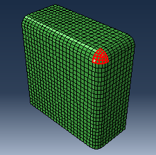
The analytic selection method for orphan element faces is based on the recognition of basic shapes in analytic geometry (such as planes, cylinders, cones, spheres, and tori), or portions of these shapes. Analytic selection attempts to recognize the logical boundaries of a set of orphan element faces that would make a recognizable geometric face.
Figure 4 illustrates analytic selection of orphan element faces. A spherical section of element faces is highlighted; this selection could not be made using any of the other selection options for multiple objects.
Figure 4. Analytic geometry selection.
After you use any of the above methods, you can select other methods in the prompt area and Shift to append more elements to your selection. You can also Ctrl on items to unselect them. In addition, you can continue to use the current method and use Shift to append elements to your selection. For more information, see Combining selection techniques.