Search controls for mapped fields | ||
| ||
Abaqus/CAE attempts to map all of your source data points and their associated field values onto points in the target model. Depending on how far away each source point lies from the nearest node on the meshed model target, Abaqus/CAE must decide whether to use or discard each source point. These decisions are based on the search tolerance distance values you choose on the Mapper Controls tabbed page.
Search controls for point cloud mapped fields
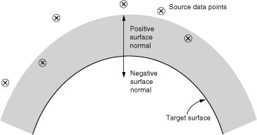
The positive and negative normal tolerance values define how far away a source data point can lie from the exterior surface of the target model. The target model surface is interpolated in the undeformed finite element model. By default, each source data point must lie within a distance calculated by multiplying the average element characteristic size in the target model by 0.05. This distance is measured along the positive normal vector of the target surface (see Figure 1).

You can change the tolerance distance values to control which source data points will be included or ignored. You can define the tolerance values as a relative fraction of the average element size in the meshed model or as an absolute distance measured in the length units being used in your model.
For any target points at which Abaqus/CAE cannot map a source point, it will substitute the Default unmapped field value entered in the Create Mapped Field dialog box. The default is zero. The default field value is applied for both point cloud data sources and output database mesh sources.
For a point cloud data source, the following options and search tolerance values are available on the Mapper Controls tabbed page:
- Tolerance type
If you choose Relative (default), the tolerance values are interpreted as a fraction (not percentage) of the average element characteristic size in the meshed model. If you choose Absolute, the tolerance values are taken as exact distances measured in the length units used in your model.
- Positive normal search distance tolerance
Any source points within this distance, as measured along the positive normal vector of the underlying geometry of the target surface, are mapped and included in the analysis (see Figure 1). This tolerance applies only to surface (not volumetric) target mapping. The default is 0.05 of the average element characteristic size in the meshed model.
- Negative normal search distance tolerance
Any source points within this distance, as measured along the negative normal vector of the underlying geometry of the target surface, are mapped and included in the analysis. This tolerance applies only to surface (not volumetric) target mapping. The default is 0.15 of the average element characteristic size in the meshed model.
- Boundary search distance tolerance
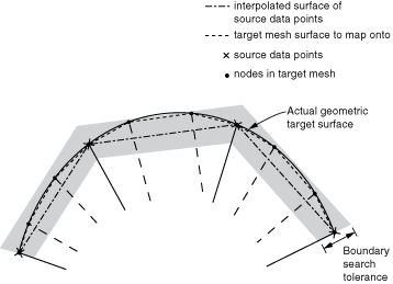
This tolerance specifies the in-plane distance within which a source data point must lie, outside the region of the elements of the meshed target model (see Figure 2). Increasing this tolerance from the default of 0.01 (of the average element size) effectively allows you to expand each target element face for the purpose of mapping. Increasing this tolerance may be helpful when the source data are a coarser mesh than the target model mesh.
The field values are interpolated when they are mapped onto the target model. The boundary search tolerance applies to both surface mapping and volumetric mapping.
Figure 2. Boundary search distance.
- Neighborhood search distance tolerance
Any source data points that lie outside the neighborhood search tolerance are ignored and are not used in the analysis. This tolerance applies to both surface and volumetric target mapping.
Abaqus/CAE uses a distance weighting algorithm to interpolate the field data values on the meshed target model. Abaqus/CAE always tries to interpolate the source values on the target. If Abaqus/CAE finds any points for which interpolation is not possible, a distance weighting algorithm is used that will take nodes within the neighborhood search distance. Distance weighting does not consider any other existing tolerances (positive/negative normal search tolerances or boundary search tolerance). You can deactivate distance weighting by using a very small neighborhood search distance, in which case Abaqus/CAE applies the Default unmapped field value at these nodes.
Abaqus/CAE makes three passes when attempting to map source points onto target points. Abaqus/CAE:
Tries to interpolate field values on the target. The neighborhood search tolerance is ignored on the first pass.
Uses the distance weighting algorithm to take source points within the neighborhood search tolerance.
For any target points that remain unmapped, Abaqus/CAE applies the Default unmapped field value.
![]()
Search controls for output database fields
The normal tolerance value defines how far away a source data point can lie from the exterior surface of the target model. By default, each source data point must lie within a distance calculated by multiplying the average element characteristic size in the target model by 0.05. This distance is measured along the normal vector of the target surface. The tolerance values are interpreted as a fraction (not percentage) of the average element characteristic size in the meshed model
You can change the default tolerance values to determine which source data points will be included or discarded.
For any target points at which Abaqus/CAE cannot map a source point, it will substitute the Default unmapped field value entered in the Create Mapped Field dialog box. The default is zero. The default field value is applied for both point cloud data sources and output database mesh sources.
For an output database source, the following options and search tolerance values are available on the Mapper Controls tabbed page:
- Normal search distance tolerance
Any source points within this distance, as measured along the positive normal vector of the underlying geometry of the target surface, are mapped and included in the analysis. This tolerance applies to both surface and volumetric target mapping. The default is 0.05 of the average element characteristic size in the meshed model.
- Boundary search distance tolerance
This tolerance specifies the in-plane distance within which a source data point must lie, outside the region of the elements of the meshed target model (see Figure 2). Increasing this tolerance from the default of 0.01 (of the average element size) effectively allows you to expand each target element face for the purpose of mapping. Increasing this tolerance may be helpful when the source data are a coarser mesh than the target model mesh.
The field values are interpolated when they are mapped onto the target model. The boundary search tolerance applies to both surface mapping and volumetric mapping.
![]()
Volume-to-surface mapping control
The Mapper Controls tabbed page of the Create Mapped Field dialog box includes the Mapping algorithm for target surface option, which lets you choose Surface or Volumetric mapping.
Your target region must be one of three types: a volume, a surface, or a set of nodes in a mesh. If the target is a volume, Abaqus/CAE always performs volumetric mapping. However, if the target is a surface or a set of nodes, you must choose the algorithm that you want Abaqus/CAE to use to apply the source data. Choosing Surface causes Abaqus/CAE to use a surface projection algorithm in which it projects the source data to target surface centroids or nodes. Choosing Volumetric causes Abaqus/CAE to use a volumetric interpolation algorithm in which it interpolates the source data to target element centroids or nodes. The distinction between the two algorithms only affects how field values from a source volume are applied to a target surface.
For the purpose of the mapping algorithm, a target surface or volume is defined in the context of either a geometric model or a mesh in Abaqus/CAE:
a volume in a geometric model is a three-dimensional cell
a volume in a mesh consists of elements
a surface in a three-dimensional geometric model is a geometric face
a “surface” in a mesh consists of element faces
Your choice of surface versus volumetric algorithm also applies when you are mapping onto nodes and the target nodes are defined by a node set (mesh-based). However, if the target nodes are defined from model geometry, Abaqus/CAE always uses surface mapping for geometric faces and uses volumetric mapping for geometric cells.
The target region is where you apply the load, interaction, boundary condition, or predefined field in your main model. If you apply the same mapped field source in two different attributes, they may have different behaviors if the target region type is different.
Volume-to-surface control for point cloud data sources
Table 1 describes the cases in which Abaqus/CAE performs volumetric or surface mapping for a point cloud data source and when you must choose between the two.
| Point cloud data source | Target region type | ||
|---|---|---|---|
| Geometric cell (3D elements or nodes) | Shell or surface/faces1 | Node set | |
| Point cloud data | Volumetric | Volumetric or surface | Volumetric or surface |
| 1 For the purpose of the mapping algorithm, a surface can be a face of a three-dimensional element. | |||
Volume-to-surface control for output database sources
Table 2 describes the cases in which Abaqus/CAE performs volumetric or surface mapping for an output database source and when you must choose between the two.
| Output database source | Target region type | ||
|---|---|---|---|
| Geometric cell (3D elements or nodes) | Shell or surface/faces1 | Node set | |
| Nodal data | Volumetric | Volumetric or surface | Volumetric or surface |
| Element-based data2 | Volumetric | Volumetric or surface | Volumetric or surface |
| Surface-based data | N/A (error) | Surface | Surface |
| 1 For the purpose of the mapping algorithm, a surface can be a face of a three-dimensional element. | |||
| 2 Output database averaging controls in the Visualization module affect the continuity of element-based source data. | |||
If the target region is a shell or surface, the volumetric algorithm interpolates field values from an entire source volume (in the output database) onto the target surface region. Alternatively, the surface algorithm projects only the field values from the surface of the source volume onto the target surface region.
The surface algorithm projects output database source data onto target surface centroids or nodes when the target surface can reference three-dimensional element faces. The volumetric algorithm interpolates source data onto target element centroids or nodes.