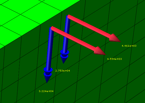
Resultant forces and moments on free body cuts in Abaqus/CAE | ||
| ||

You can define the nodes and elements that comprise the cross-section using processes that closely resemble the definition of display groups. Abaqus/CAE enables you to specify the components of the cross-section by including surfaces, display groups, and elements or nodes by number; and you can pick items from the viewport, either by feature angle or individually. See Creating or editing a free body cut for detailed instructions. After you define the physical components of your free body cross-section, you can set the location of the summation point (about which resultant moments are taken), and you can indicate the coordinate system transformation that applies when vectors are displayed in component form.
Cross-sections can be created along mesh boundaries only; you cannot specify a cross-section along an arbitrary plane. You can create and display free body cuts only in the Visualization module.