Allowing for branching in offset solid meshes | ||
| ||

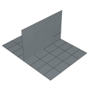
To help you mesh this configuration, Abaqus/CAE provides the option to copy the elements in the region of the branch to a set.
You can then do the following:
-
Use display groups to remove the set containing elements in the region of the branch from the orphan mesh.
-
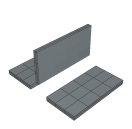
Create offset solid meshes from the non-branching regions that remain, as shown in Figure 2.
Figure 2. Create offset solid meshes from the non-branching regions.
-
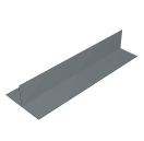
Use display groups to show only the set containing the branch, as shown in Figure 3.
Figure 3. Use display groups to show only the set containing the branch.
-
Create an offset solid mesh from one side of the branching region. Take care that the offset direction is correct (Abaqus/CAE indicates the offset direction by coloring the element faces). In addition, do not delete the base shell elements until you have finished offsetting the branch.
-
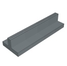
Create an offset solid mesh from the other side of the branching region, as shown in Figure 4.
Figure 4. The offset mesh in the branching region.
-
Use display groups to show both regions.
-
Use the merge nodes tool in the Edit Mesh toolset to merge the offset meshes created in Steps 2, 4, and 5.