Defining the Design Area for Topology Optimization | ||
| ||
Define the Design Area in Tosca ANSA® environment
- Use a predefined node or element group.
- Create a node or element group directly in the model to use as Design Area.
In this example, you define the elements for the Design Area directly in the model.
In the SET HELP dialog, select
 > New.
The Modifying SET: Untitled (Id:1) dialog opens.
Press the left mouse button and enclose the whole model in a frame:
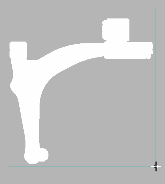
Tip: To rotate the model, hold CTRL and use your left, right, and middle mouse buttons. Hold the right mouse button and deselect 4 parts as shown in the figure:
It is recommended to rotate the model in plane and zoom in and out to make the selection more accurately.
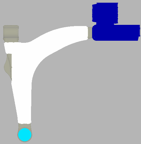
If you want to check your group selection, select and activate
 Highlighting.
Your group definition will be marked in color in the model.
![]()
Define the Design Area in Tosca Structure.gui
![]()
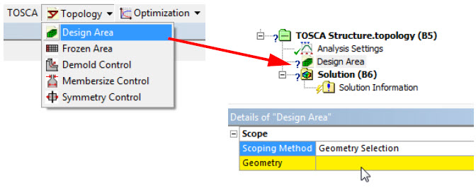
Define a Design Area in Tosca Extension for ANSYS® Workbench
In the Design Area dialog, select Geometry as shown in the following figure:
The part of the geometry that is assigned will be optimized. It is also possible to assign a predefined Named Selection.