Slices through 3D models and border of 2D models | ||
| ||
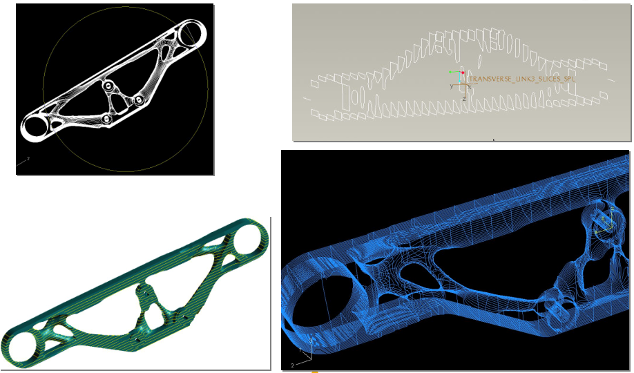 With Courtesy of Audi AG |
The location of slices is decided by the parameters SLICE_NORMAL and SLICE_NUMBER. For each SLICE_NORMAL entry, a series of parallel planes orthogonal to the vector given by this parameter is generated. The model is spanned between the first and the last section planes, and the remaining planes are located equidistantly between them. The total number of planes in each direction is given by SLICE_NUMBER parameter.
Then, if SLICE_FORMAT = igs_polygon or SLICE_FORMAT = cli is specified, the polygons resulting from the intersection of the model with the section planes are saved in IGES or CLI format resp. In case of SLICE_FORMAT = igs_curves, the points of the polygons are used as the support points for uniform cubic B-splines, that are in turn saved in IGES format.
Output parameters of Tosca Structure.smooth |
||||||
|---|---|---|---|---|---|---|
Para-meter |
Value |
Description |
Supported by |
|||
TAe |
GUI |
TExt |
||||
TS.pre |
TS.smooth |
|||||
SLICE_ NUMBER |
Nonnegative integer; default: 0 |
Number of parallel section planes that define the slices. If set to 0, no slices are saved |
x |
x |
x |
x |
SLICE_ NORMAL |
<x>,<y>,<z> with real values x, y, z |
Normal to the section planes. The real values x, y, z that are not all equal to zero should be separated by commas; spaces before or after the commas are allowed. Multiple SLICE_NORMAL parameters are allowed: slices in all directions that are specified by SLICE_NORMAL are saved together to the output file. |
x |
x |
x |
x |
SLICE_ FORMAT |
default: igs_polygon igs_polygon (file name: <name>_slices.igs) igs_curves (file name: <name>_slices_spl.igs) cli (file name: <name>_slices.cli) all |
The format used for saving the slices igs_polygon: polygons saved using cubic parametric splines for each segment (IGES block 112) igs_curves: curves obtained by interpolation using uniform cubic splines (IGES block 126) cli: polygons saved in common layer interface format all: save in all formats mentioned above |
x |
x |
x |
- |
BORDER |
yes no default: no |
If set to yes, the border of the shell element model will be saved according to the format defined by SLICE_FORMAT parameter; the file name is the same as for slice output, with ’slices’ replaced with ’border’. |
x |
x |
x |
x |
IGES_UNIT |
in: inches mm: millimeters ft: feet mi: miles m: meters km: kilometers mil: mils um: microns cm: centimeters uim: microinches default: mm |
Unit used for output in IGES format. Note that the same unit is used in the case that the model is saved in IGES format. |
x |
x |
- |
x |
For shell element models, using will BORDER = yes setting with SLICE_FORMAT = igs_polygon or SLICE_FORMAT = igs_curves results in saving the border (outline) of the resulting model in IGES format.
| Important:
Note that the generation of slices is only available for solid models, and is skipped for shell element models. Accordingly, the output of the border can only be done for shell element models. Also, if the slices are used along with the output in VTFX format, the section planes are included in VTFX files so that the slices can be visualized using Tosca Structure.view: it suffices to open the VTFX file and to hide the surfaces using Display > Part Attributes... menu command. |