Isosurface and smoothing parameters | ||
| ||
Following parameters control the generation and the smoothing of the isosurface. They are used when the isosurfaces of the material distribution resulting from topology optimization are calculated: in this case, the parameter TASK is set to iso (single isosurface) or all_iterations (isosurfaces for all iterations). Additionally, the parameters SELF_INTERSECTION_CHECK and MIN_ANGLE are used during the data reduction that is described in details in the next section.
Isosurface generation and smoothing parameters of Tosca Structure.smooth |
||||||
|---|---|---|---|---|---|---|
Parameter |
Value |
Description |
Supported by |
|||
TAe |
GUI |
TExt |
||||
TS.pre |
TS.smooth |
|||||
ISO_VALUE |
Real value between 0 and 1 Default: 0.3 |
Isovalue; is used to determine the positions on the element edges where the new nodes are created. Larger values lead to models with smaller volume. See below for an example. |
x |
x |
x |
x |
SMOOTH_ CYCLES |
Non-negative integer number Default: 5 |
Number of smoothing cycles; if set to 0, no smoothing is performed. Larger values lead to smoother models, but may cause the narrowing of thin components. |
x |
x |
x |
x |
ORIGINAL_SURFACE_SMOOTHING |
off (original surface is not smoothed) shrink (limited original surface smoothing) full (original surface is smoothed) default: off |
Defines if the smoothing of the original surface is to be performed. If set to shrink, the original surface gets smoothed by moving its nodes towards the inside of the model only, so that the restrictions on the design region are not violated. |
- |
x |
x |
- |
SELF_ INTER-SECTION_ CHECK |
off (no checks) check (check once) runtime (check always) iterative (first run without check, rerun if needed) Default: iterative |
Defines if the self-intersection checks are to be performed during the isocut, smoothing and data reduction. See below. |
x |
x |
x |
- |
MIN_ANGLE |
Real value between 0 and 90 Default: 15 |
Defines the minimal angle of the triangles that result from the smoothing and data reduction; triangles with smaller angles may be present if they are created during the isocut. Too large value may prevent the smoothing; too small value may lead to degenerated triangles. |
x |
- |
x |
- |
All parameters have default values that are useful in most cases. However, these parameters affect the appearance of the isosurface as described below.
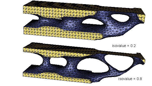
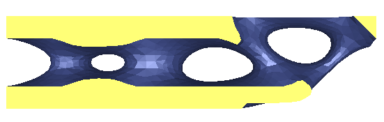
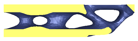
The isovalue specified using the parameter ISO_VALUE defines the position between the elements with zero and maximal material value where the isosurface is constructed. More precisely, the interpolated material values are first found for each node, and then the new nodes are constructed on the edges that have varying material values (i.e., material value for one end is less than and for the other one larger than the isovalue). The ratio in which the edge is subdivided by the new node is defined by the iso-value in respect to the material values of the ends of the edge, but is limited to a range from a to 1-a with a constant value a (currently 0.3) in order to prevent edges of very small lengths. As the result, increasing the isovalue leads to shifting the isosurface towards the inside of the model, thus the model volume decreases.
Note: For the structures with thin components, it is not recommended to use large isovalues (larger than 0.7), since the structure might become disconnected.
See the folslowing figures for example of how the isovalue influences the result.
 |
| Important:
In case that the structure becomes disconnected, it is advised to repeat the calculation with smaller isovalue. Still, if the model contains a single layer of elements or a string of elements connected by nodes only, the isosurface will probably be disconnected for any isovalue. In this case, it is recommended to repeat the topology optimization with adjusted minimal thickness of components that can be specified by choosing the minimal member size in DVCON_TOPO. Another possible solution is to use a refined mesh. |
After the isocut is done, the surface smoothness is generally not sufficient. Therefore, the iterative smoothing is performed by displacing the nodes created in the isocut. The smoothing is done in cycles; the number of cycles is determined by the parameter SMOOTH_CYCLES.
The conditions for a node displacement to be accepted is that the angles of resulting triangles are larger than a certain value specified by the parameter MIN_ANGLE, and, if requested, that no surface self-intersections occur after the displacement.
The second check is not done if SELF_INTERSECTION_CHECK parameter is set to off or check; the difference in these cases is that, in case this parameter is set to check, the self-intersection test is performed once for the entire model after the smoothing and data reduction are made, and the user receives the information about the number of intersecting faces as well as a VRML file containing these faces. In case that SELF_INTERSECTION_CHECK parameter is set to iterative, the smoothing is first performed without the self-intersection checks, and then is redone if the self-intersections appear after the smoothing.
| Important:
Note that in case of SELF_INTERSECTION_CHECK parameter set to iterative or runtime, similar self-intersection checks are done for isocut and data reduction as well; however, in rare cases, self-intersections that occur during the isocut cannot be prevented, and they are likely to remain after the smoothing and data reduction are done. |
In order to achieve smoother surfaces, higher value of SMOOTH_CYCLES parameter should be used. However, this leads to the increase of the computation time that might be noticeable especially in the case that the self-intersection test is turned on. In practice, 5 to 10 smoothing cycles are usually sufficient. Further smoothing might have a negative effect of contracting thin components; in certain cases, the smoothing has to be turned off by setting SMOOTH_CYCLES to 0.
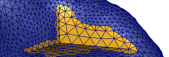
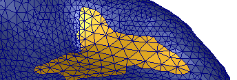
See the following figure for an example of smoothing with various numbers of smoothing cycles:
0 smoothing cycles (smoothing turned off) |
|
3 smoothing cycles |
|
10 smoothing cycles |
A higher number of smoothing cycles can cause some shrinkage effects on the surface that is being smoothed. Especially areas with a high curvature can be changed drastically. If you want to prevent these effects, the parameter SHRINKAGE_CORRECTION can be set to YES. Activating the correction will reduce the shmoothing efficiency slightly. A higher number of smoothing cylces may be necessary.
 |
shrinkage correction deactivated |
 |
shrinkage correction activated |
The parameter ORIGINAL_SURFACE_SMOOTHING defines if the original surface (that is the part of the surface of original elements, in contrast to the new surface produced by isocut) should be smoothed.
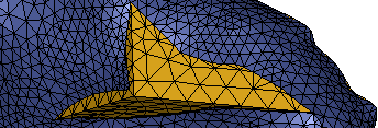 |
ORIGINAL_SURFACE_SMOOTHING = off |
 |
ORIGINAL_SURFACE_SMOOTHING = shrink |
 |
ORIGINAL_SURFACE_SMOOTHING = full |
If it is set to off, the original surface remains unchanged. In most cases, this is desired since the surface nodes might have some additional information (e.g. forces or boundary conditions) associated with them. However, the resulting surface will be smoother if the original surface gets modified as well. To do this, set ORIGINAL_SURFACE_SMOOTHING to full.
The third option ORIGINAL_SURFACE_SMOOTHING = shrink allows modifying the original surface, but in a way that the new surface does not occupy the region beyond the initial design. This is achieved by prohibiting the nodes to be moved towards the outside of the model.
| Important:
Note that the surface of the frozen regions that are chosen using GROUP_SURFACE commands is not modified even if the original surface smoothing is turned on. |