Center of Gravity | ||
| ||
Parameter Name |
Formula |
|---|---|
CENTER_GRAVITY_X |
|
CENTER_GRAVITY_Y |
|
CENTER_GRAVITY_Z |
Analysis Independent Design Response
For the center of gravity the following table shows the allowed combinations between strategy and the items OBJ_FUNC and CONSTRAINT with C for controller and S for sensitivity based optimization.
TOPO |
SHAPE |
BEAD |
SIZING |
|
|---|---|---|---|---|
OBJ_FUNC |
S |
S |
S |
|
CONSTRAINT |
S |
S |
S |
The center of gravity for the three directions is defined by CENTER_GRAVITY_X, CENTER_GRAVITY_Y and CENTER_GRAVITY_Z, respectively. The center of gravity and the moments of inertia can be defined as a DRESP (design response) and as a VARIABLE in the sensitivity-based topology, bead and sizing optimization. For shape optimization the center of gravity and the moments of inertia can only be defined as a VARIABLE which means that the values can only be used for output or control purposes.
Both the center of gravity and the moments of inertia can be defined as a design response for the entire structure or for a part of the entire structure, e.g. some specific components. This is done using the command EL_GROUP.
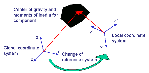
The center of gravity and the moments of inertia are per default calculated in the global coordinate system. However, the user has the option to calculate the center of gravity and the moments of inertia in a local coordinate system. The local coordinate system is defined in the design response using the command CS_REF. For the calculation of the center of gravity both the directions and origin of the local coordinate system is used as reference whereas for the moments of inertia the directions of the axes of the local coordinate system is applied, see the following figure. The global coordinate system is applied if no local coordinate system is defined in the design response (DRESP). The volume for which the center of gravity is calculated is defined using EL_GROUP.
 |
![]()
Remarks
- Only elements of the element group (EL_GROUP) listed in the tables of supported element types will be applied in the calculation of center of gravity.
- The physical density defined in finite element input deck will be used in the calculation for the center of gravity.
- The moments of inertia for shell and membrane elements are calculated as true 3D elements in SIMULIA Tosca Structure using the thickness defined in the properties of the shell and membrane elements in the finite element deck. Some finite element solvers and postprocessors calculate the moments of inertia for shell and membrane elements as 2D elements without thickness.
- The physical density defined in finite element input deck will be used in the calculation for the center of gravity and in the calculation for the moments of inertia.
- Internally, SIMULIA Tosca Structure calculates the center of gravity and the moments of inertia using more digits than can be observed in the finite element input deck. A slight difference (<1%) between the center of gravity and the moments of inertia calculated using SIMULIA Tosca Structure and the finite element solver might be present.
- When SIMULIA Tosca Structure calculates the center of gravity and the moments of inertia only the elements shown in the tables of supported element types are included in the calculation. This might lead to a significant difference between the center of gravity and the moments of inertia calculated by SIMULIA Tosca Structure and the center of gravity and the moments of inertia calculated by the finite element solver, e.g. if several beam elements are included in the calculation of the center of gravity and the moments of inertia.
- The coordinate system for the center of gravity and the moments of inertia is always interpreted as a Cartesian (rectangular) coordinate system, even if a cylindrical or spherical coordinate system was defined. To get close to a non-Cartesian coordinate system you can define adequate "box constraints" using several constraints (e.g. in x- and y-direction for a cylindrical coordinate system).
![]()
Definition
The design response (DRESP) for the center of gravity in the x-direction is defined like
DRESP
 ID_NAME = ...
 DEF_TYPE = SYSTEM
 TYPE = CENTER_GRAVITY_X
 EL_GROUP = ...
 CS_REF = ...
END_
where the local coordinate definition (CS_REF) is optional. Default is global coordinate system.
The design response (DRESP) for the center of gravity in the y-direction is defined like
DRESP
 ID_NAME = ...
 DEF_TYPE = SYSTEM
 TYPE = CENTER_GRAVITY_Y
 EL_GROUP = ...
 CS_REF = ...
END_
where the local coordinate definition (CS_REF) is optional. Default is global coordinate system.
The design response (DRESP) for the center of gravity in the z-direction is defined like
DRESP
 ID_NAME = ...
 DEF_TYPE = SYSTEM
 TYPE = CENTER_GRAVITY_Z
 EL_GROUP = ...
 CS_REF = ...
END_
where the local coordinate definition (CS_REF) is optional. Default is global coordinate system.
![]()
Examples of Commands for Center of Gravity
E.g. the design response (DRESP) for the center of gravity for the y-direction of the entire structure (ALL_ELEMENTS) calculated in the global coordinate system is defined like
DRESP
 ID_NAME = DRESP_COG_Y_GLOBAL
 DEF_TYPE = SYSTEM
 TYPE = CENTER_GRAVITY_Y
 EL_GROUP = ALL_ELEMENTS
END_
E.g., the definition of the design response (DRESP) for the center of gravity for the y-direction of the substructure called EL_GROUP_2 is calculated in the local coordinate system number 23 like the following:
DRESP
 ID_NAME = DRESP_COG_X
 DEF_TYPE = SYSTEM
 TYPE = CENTER_GRAVITY_X
 EL_GROUP = EL_GROUP_2
 CS_REF = CS_23
END_