Restrictions (DVCON_SHAPE) Overview | ||||||
|
| |||||
To meet functional and manufacturing requirements, it is usually necessary to limit the solution area and therefore the independence of the design nodes. Unrestricted shape optimization can produce trivial results. For example, if the shape of a shaft shoulder under axial tensile stress is optimized without restricting the design nodes, a smooth beam will arise that will not be able to fulfill the original function.
To achieve the best results the rule: "As much flexibility as possible, as few restrictions as necessary!" should be followed. The possible restrictions are the specification of an allowed displacement area by limiting the directional amount of optimization displacement and the specification of variation and frozen areas. It is also possible to influence the allowed displacement direction by limiting the displacement to specific coordinate directions. In addition, the optimization displacement of a node can be made dependent on the optimization displacement of another node. The definition of the design variable constraints for shape optimization is done with the DVCON_SHAPE command.
The following restrictions are available for shape optimization, but not all are applicable for both optimization attempts:
- Restriction of the amount of displacement
- Maximum and minimum member size
- Displacement check against solids
- Displacement check against elements of an element group
- Restriction of the displacement direction
- Restricting the displacement to a slide surface
- Assignment of a coupling condition
You are free to use the non-applicable design variable constraints for sensitivity based shape optimization as well. But in that case the geometry is changed without letting the optimization module acknowledge this change which might or might not lead to convergence problem for (complex) models.
 |
Note:
- Some of the design variable constraints for shape optimization can be interpreted as side constraints or bounds (design variable boundaries) in the same way these terms are used in standard optimization nomenclature.
- Some of the design variable constraints for shape optimization relate not only to the design variable itself but also to the corresponding optimization displacement vectors (or the design coordinates). The term ‘design variable constraint’ in this case should be interpreted in a more general sense.
- In contrast to the DVCON_SHAPE parameter, which has a direct effect on the individual design variables, the CONSTRAINT parameter defines a constraint for the optimization job that affects the functional relationships of several design variables (e.g. volume constraint).
- The activated DVCON_SHAPE entries are executed in the order in which they are referenced in the OPTIMIZE command or defined in Tosca ANSA® environment. The individual DVCON_SHAPE entries are checked independent of one another, i.e., a DVCON_SHAPE entry always overrides the preceding DVCON_SHAPE entry. If mutually independent restrictions are declared all restrictions are observed. If mutually dependent restrictions are declared the user must select an order of execution that is logical and specific for the problem.
- The restricted nodes are checked at the beginning and the execution stops if the defined constraint is not fulfilled (CHECK_SLIDE, CHECK_LINK). This behavior can be switched off with the parameter FEASIBLE_START=NO. But for example if the surface described node group is not stampable and this check is switched off the restriction enforces the stampable surface.
This section only contained a general overview of the command forms without going into detail about the exact syntax and operations of the individual restrictions. In the following sections the individual restrictions are described in more detail.
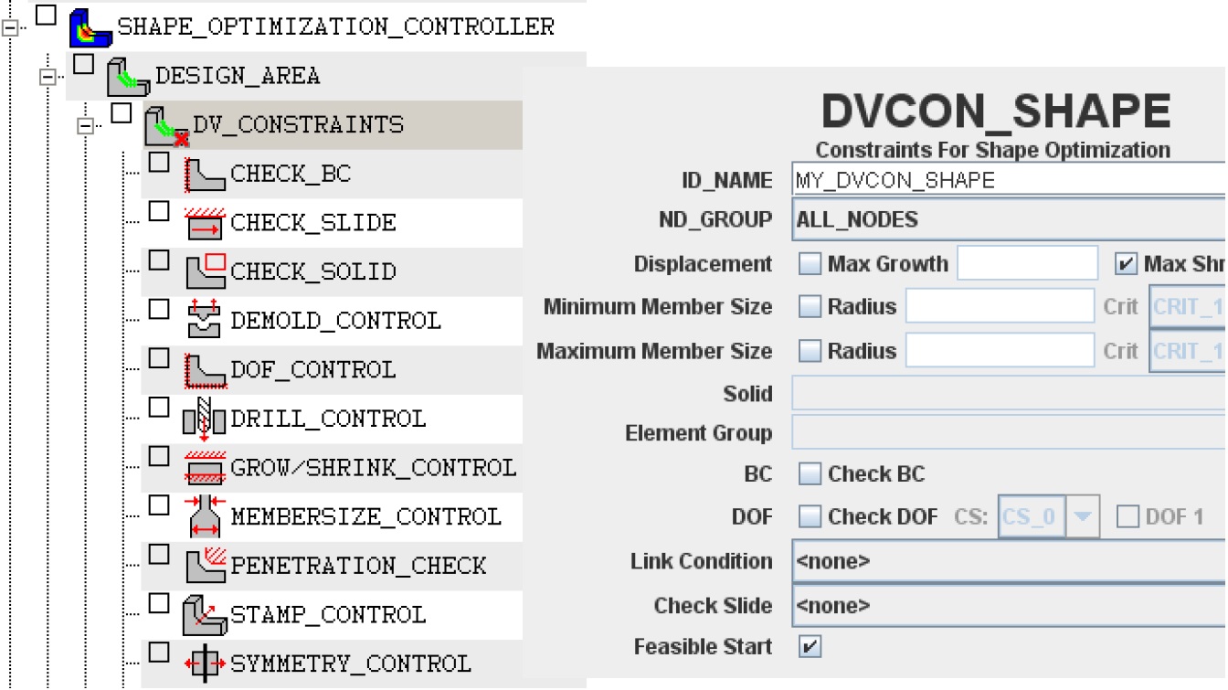
Definition in Tosca ANSA® environment
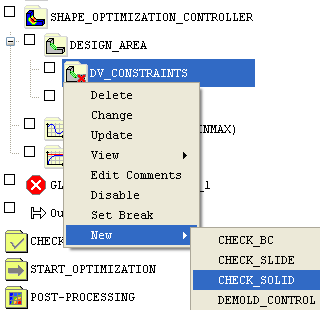
- Choose (or by Edit command on an already existing item that corresponds to the design variable constraint).
- In the appearing dialog, you can choose a node group to be restricted and define further settings.
 |
![]()
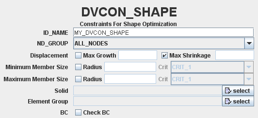
Definition in Tosca Structure.gui
- Choose in Tosca Structure.pre.
- In the DVCON_SHAPE dialog, choose the node group for the restrictions and define further settings:
 |
![]()
Command syntax
Each DVCON_SHAPE definition has a name (ID_NAME parameter) and references a previously defined node group (ND_GROUP parameter). The name is required to subsequently activate the DVCON_SHAPE definition when specifying the optimization job (see OPTIMIZE command). The node group specifies the node area where the restriction is in effect.
The following parameters define the individual restrictions for shape optimization:
- CHECK_GROW, CHECK_SHRINK: Restriction of the amount of displacement
- CHECK_MAX_MEM, CHECK_MIN_MEM: Definition of a maximum and minimum member size
- CHECK_SOLID: Check the displacements against geometric primitive solids
- CHECK_ELGR: Check the displacements against elements of an element group
- CHECK_BC, CHECK_DOF: Restriction of the displacement direction
- CHECK_SLIDE: Restricting the displacement to a slide surface
- CHECK_LINK: Assignment of a coupling condition
A DVCON_SHAPE command using all of the individual restrictions appears as follows:
        DVCON_SHAPE

          ID_NAME =name_of_dvcon_shape
          ND_GROUP = name_of_node_group
          CHECK_GROW =<max_grow_value>
          CHECK_SHRINK =<max_shrink_value>
          CHECK_MAX_MEM  =<radius>
          CHECK_MIN_MEM  =<radius>
          CHECK_SOLID = name_of_solid
          CHECK_ELGR = name_of_element_group
          CHECK_BC = cs_name,[FREE|FIX],[FREE|FIX],[FREE|FIX]
          CHECK_DOF =[YES|NO]
          CHECK_SLIDE = name_of_link_shape
          CHECK_LINK = name_of_link_shape
          FEASIBLE_START =[YES|NO]

        END_
Note:
- It is possible to define several individual CHECK_* restrictions within a DVCON_SHAPE command. The order of the execution of the individual restrictions within a DVCON_SHAPE command appears as follows: CHECK_GROW/ CHECK_SHRINK, CHECK_MAX_MEM, CHECK_MIN_MEM, CHECK_SOLID, CHECK_ELGR, CHECK_BC, CHECK_DOF, CHECK_SLIDE, CHECK_LINK . The individual restrictions are checked independent of one another, i.e., an individual restriction always overrides the preceding restriction.
- It is possible to define several design variable constraints using the DVCON_SHAPE command. Each DVCON_SHAPE definition must have its own unique name.
Important:
|