Restricting displacement directions | ||||||
|
| |||||
| Applicable for | Controller (SHAPE_CONTROLLER) | Sensitivity (SHAPE_SENSITIVITY) |
|---|---|---|
| CHECK_BC | OK | OK |
| CHECK_DOF | OK | (OK) - only CHECK_DOF = CS_0, FIX, FIX, FIX |
| RESTRICT_ON_SURFACE | OK | -* |
To deviate from the automatically determined displacement direction for design nodes as well as for mesh smoothing nodes, every translational degree of freedom can be fixed for any node in a freely defined coordinate system. In this way, a node can be restricted to move on one plane only (fixed to one value) or to move within a displacement vector (fixed to two values). The restriction of all three translational degrees of movement is equivalent to a constraint of the node in the shape optimization.
The displacement boundary condition must be unique. In contrast to FE boundary conditions for several load cases, the total of all the supports for all load case are considered as supports in the optimization. A prescribed node displacement as an optimization boundary condition is also not permitted. SIMULIA Tosca Structure.shape offers the user two possibilities for restricting the displacement directions of nodes.
The full or partial fixation of nodes is the most common and most important type of restriction; it is practically used in every optimization model. The most efficient method for defining the displacement restrictions in the FE preprocessor is as an extra load case in the analysis model and then load it via the FE interface in the optimization preprocessor. The interface must first be activated with the OPTIONS, BC = ... parameter. In this way all node fixations for the optimization model can be defined in advance in the FE preprocessor. The fixation is always based on the FE displacement coordinate system of the node. The parameter
CHECK_BC = YES
activates the node fixations of the node group (ND_GROUP
parameter) that are loaded in the FE model. Fixations that reference
nodes not contained in the node groups are not activated. To prevent
loaded fixations from being activated enter:
CHECK_BC = NO
If it is necessary to restrict other displacement directions in addition
or at a later stage, this can be accomplished with the CHECK_DOF
parameter in the menu DOF_Control (Tosca ANSA® environment)
or the field DOF (Tosca Structure.gui).
This restriction is applied to a node group.
The coordinate system must also be defined or loaded. With the parameter
CHECK_DOF = <cs_name>, FIX/FREE, FIX/FREE, FIX/FREE
all the displacements of all nodes in the node group selected with ND_GROUP
are fixed (FIX) or free (FREE) relative
to the specified coordinate directions of the coordinate system <cs_name>.
Either FREE or FIX is allowed for each
coordinate direction.
Note:
- The restrictions CHECK_BC or CHECK_DOF can be applied to both: surface nodes and inner nodes.
- The essential difference between CHECK_BC and CHECK_DOF is: CHECK_BC is read in through the FE interface whereas CHECK_DOF is defined in the optimization preprocessor. With CHECK_BC each node generally has its own fixation in its own displacement coordinate system, whereas with CHECK_DOF all nodes of the node group are all fixed in the same coordinate system.
- For sensitivity based shape optimization CHECK_DOF will work in most cases. However, it is not fool proof, meaning that SIMULIA Tosca Structure might run into convergence problems with an inept CHECK_DOF restriction. That is the reason why only CHECK_DOF = CS_0, FIX, FIX, FIX is officially supported.
Restrict nodes on surfaces
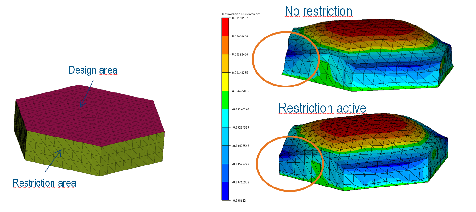
The RESTRICT_ON_SURFACE constraint restricts nodes to move only on the surface. Movements in the normal direction are suppressed. This is especially handy for variation areas (areas that are not part of the design area, but are allowed to move to allow shape variations).
The following figure shows a typical example for the use of this restriction applied on the green area. The red area in the figure is the design area. Then the green area must not be fixed to allow the edges to move. But you also do not want these nodes to move outward of the surface plane. You could apply the surface restriction here. The same effect can be achieved with CHECK_DOF commands, but one command for each side (six in total) is needed.
Example:
            DVCON_SHAPE
              ID_NAME             = MY_SURFACE_RESTRICTION
              ND_GROUP            = GREEN_AREA
              RESTRICT_ON_SURFACE = YES
            END_
Some theory: The nodes are restricted in their movement by projecting them on the plane described by their normal vector and the position on the start model. This is also the reason why this method works best for plane surfaces. If edges are detected, the nodes are projected on the planes adjacent to the edge, which allows the node to move only along the edge or to not move at all in case of corners.
* Some words to the usage in combination with Shape sensitivity: This feature is not blocked for the use with shape sensitivity, but it is also not fully supported. Applying this feature to nodes outside the design area, no big drawbacks are expected. However, applying it to design nodes might lead to convergence problems: The node position is changed without letting the optimizer know about this change. Depending on the model and on the amount of change, everything might go well - or not.