About Prevention of Undercuts in the Model | ||||||
|
| |||||
In many cases where bending and torsion loads are applied, the topology optimization results in models with hollow areas or models with undercuts that make the manufacturing close to infeasible. In order to convert the result of non-restricted topology optimization into a manufacturable design, a lot of manual changes are necessary. These changes might modify the mechanical properties dramatically. The solution for this problem is to include the manufacturing constraints directly in the topology optimization.
The following figure shows the difference between two optimization results: without manufacturing constraints (left) and with casting constraint to prevent undercuts (right):
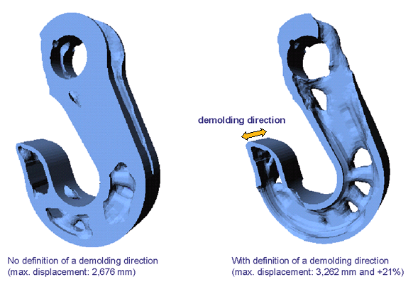 |
The formation of cavities and undercuts during the topology optimization can be prevented by using the casting constraint in the design variable constraint definition. This simplifies significantly the transfer of topology optimization results into manufacturable components. Solutions are limited as in the case of all other kinds of restrictions.
| Tip: Usually, it is better to carry out the optimization without manufacturing restrictions first, and then to perform a second optimization with manufacturing restrictions. |
Demold restriction definition
For a definition of a demold restriction, two element groups are needed:
- The first group is the "casting group" which consists of the elements where the restriction is active. It should be a subset of the design element group.
- The second one is the "check group": when it is checked if an element
is allowed to be removed, this test is performed with respect to the
elements in the check group. The check group should include all elements
of the casting group.
Note: The specified check group is the group of elements against which a removal of an element is examined. This group has always to contain at least all elements of the DVCON group. The elements outside of the DVCON group are treated as a barrier if there are elements in the check group that do not belong to the DVCON group. This means that the elements in the optimization group cannot be removed "through" these other elements. For example, in the optimization of an engine bracket, a part is retained in the analysis model. The check group is to be restricted to the engine bracket because during its manufacture, the engine block is not significant for its deformation. If the engine bracket is attached to the engine, the engine block must be included in the CHECK_GROUP, otherwise elements from the optimization space are removed that have been ”pulled” by the engine block.
The check if a removal of an element results in a hole or an undercut requires that the check direction is specified. Since only one check direction for an element is allowed, casting groups of two different demold restrictions must not intersect.
![]()
Check Types
There are four types of the check for undercuts and cavities:
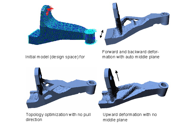
- Using a pull direction without the middle plane (MID_PLANE = NONE). Only the pull direction is defined. A fictitious middle plane lies outside of the component so that pulling takes place in only one direction.
- Using a pull direction with a fixed middle plane (MID_PLANE = POINT) A middle plane is defined by a point and the pull direction (vector perpendicular to the middle plane). It is checked that the component is demoldable in both directions away from the middle plane.
- Using a pull direction and the automatically defined middle plane (MID_PLANE = AUTO). SIMULIA Tosca Structure determines the optimal position of the middle plane for each area.
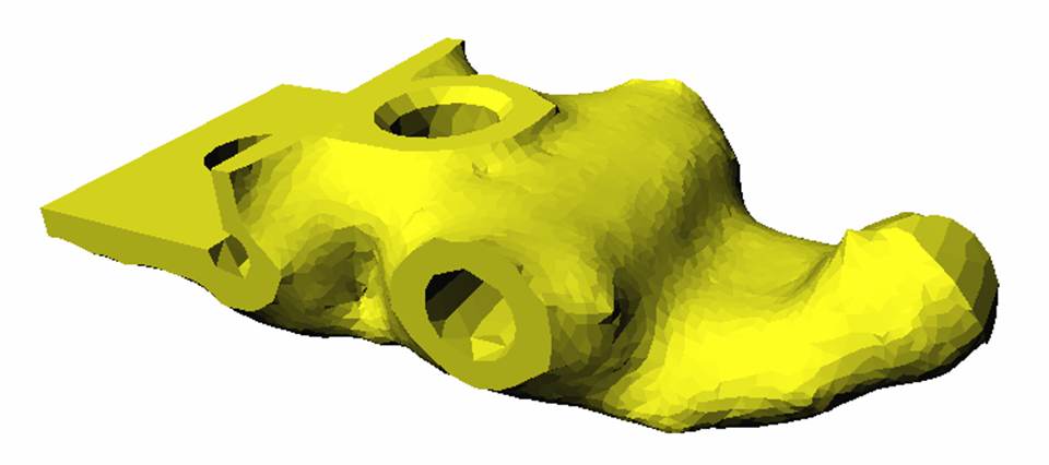
- Using the normal direction to the surface (MID_PLANE = SURFACE) For
each element, the direction is the normal at the surface point nearest
to the element (only the surface of the elements from the casting group
is considered).
The check type SURFACE is useful for models where the pull direction is not already known as shown in the following figure:
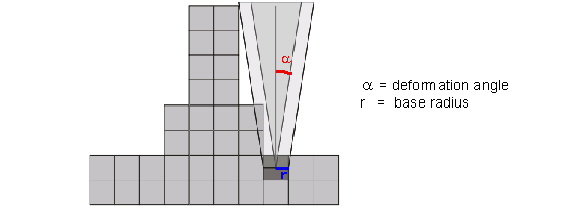
A pull direction vector (PULL_DIR) has to be defined for the types 1-3. The deformation angle (ANGLE) defines the necessary angle needed for ejection. Values between 0° and 20° are permitted. Checking the pull direction is made with the help of a pull cone starting at the centroid of the respective element. That the pull direction is maintained is checked using the pull cone with a certain base radius. This radius is based on the average element size and is usually determined from the model.
![]()
Example: Deformation angle
The following figure shows a pull cone with a deformation angle centered at element enlarged by base radius r.
 |
The specification of this RADIUS is optional and is only necessary for models that have elements of very different sizes. If a value is specified, it should be larger than approximately 50% of the average element edge length.
The following figure shows an engine mount with and without manufacturing restrictions:
 |
Members of the specified element group are only modified if they can be removed from the model in the pull direction, so that internal cavities and recesses cannot be formed.
Important:
|