About the Shaft Drill Example | ||
| ||
About the Model
The model is a shaft with a transverse drilling. Symmetrical aspects allow for modeling of only a half model and symmetry boundary conditions are applied to the symmetry plane. The drilling hole has to be maintained during the optimization procedure. Drilling combines a turning surface which has to be demoldable against the feed direction of the die. If no restrictions are enforced, an oval shaped hole would be the result of the optimization as the stress distribution is not symmetrical. The following figure illustrates the boundary conditions and the stress distribution of the initial model.

The definition of the following groups is required for the optimization task:
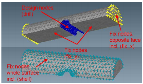
![]()
Procedure Summary
| Model: | shaft_drill.ext |
| Design Area: | Node group drill |
| CS_DEF | New cylindrical coordinate system, defined by rotating the global CS by 90° around the global y-axis and origin with coordinates (0,0,5) |
| Design Variable Constraint: | Apply boundary conditions for all nodes |
| Design Variable Constraint: | Drilling restriction for the design nodes in direction of the global positive z-axis |
| Design Variable Constraint: | Fixation of the displacement along the global x-axis for node group fix_x |
| Design Variable Constraint: | Fixation of the displacement along the global y-axis for node group fix_y |
| Design Variable Constraint: | Fixation of the displacement along the x-axis of the new cylindrical CS for node group shell |
| Mesh Smooth: | Mesh smoothing of all elements, while free surface nodes remain fixed up to the fourth layer |
| Objective: | Minimize the maximal von Mises stresses in the design area |
| Settings: | Read boundary conditions for all nodes |
| Stop Condition | The global stop condition is set to 6 iterations |