About the Carrier Stamp Example | ||
| ||
About the Model
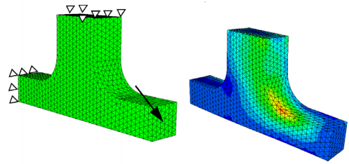
This is the same model as the previous example and the objective function and constraints are the same. In this case, the finite element model is built using a tetrahedral mesh. Further, a constraint which enforces manufacturability by means of stamping (symmetry is also possible but not shown here) is required. The standard coupling conditions may not be used, as the surface nodes of the mesh are not lying exactly in the direction of stamping. The following figure illustrates the mesh, boundary conditions and the stress distribution of the initial model.
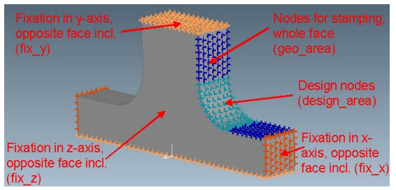
For arbitrary meshes, the surface nodes may not be grouped using the standard link conditions. In this case, a geometric and mesh independent approach has to be used. The user has to specify a surface node group which describes the stamping surface. In addition, the stamping direction has to be defined using a coordinate system. The stamping surface is described by the stamping direction and the nodes on this surface produce a manufacturing curve. When the manufacturing curve is moved along the stamping direction, the stamping surface is described. SIMULIA Tosca Structure automatically determines the producing curve for a given link domain.
The definition of the following groups is required for the optimization task:
![]()
Procedure Summary
| Model: | carrier_stamp.ext |
| Design Area: | Node group design_area |
| Design Variable Constraint: | Apply boundary conditions for all nodes |
| Design Variable Constraint: | Stamping restriction for node group geo_area in direction of the global positive z-axis |
| Design Variable Constraint: | Fixation of the displacement along the global x-axis for node group fix_x |
| Design Variable Constraint: | Fixation of the displacement along the global y-axis for node group fix_y |
| Design Variable Constraint: | Fixation of the displacement along the global z-axis for node group fix_z |
| Mesh Smooth: | Mesh smoothing of all elements, while free surface nodes remain fixed up to the third layer |
| Objective: | Minimize the maximal von Mises stresses in the design area |
| Settings: | Read boundary conditions for all nodes |
| Stop Condition | The global stop condition is set to 5 iterations |