About the Plate Example | ||
| ||
About the Model
In the following figure the initial model is illustrated. The boundary is fixed and the center is loaded with a pressure load
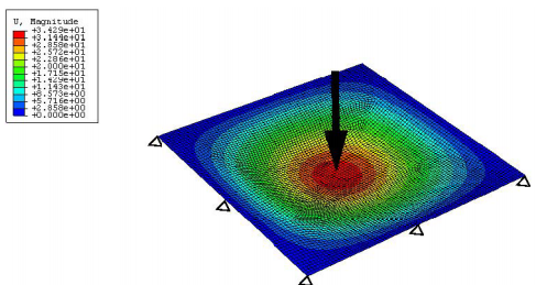
All nodes of the model should be used for optimization. The boundary nodes, which are fixed in the finite element model, should also be fixed during optimization. Therefore, the node fixations of the finite element model are activated for the optimization procedure.
![]()
Procedure Summary
| Model: | plate.ext |
| Design Area: | All nodes |
| Design Variable Constraint: | Apply boundary conditions for all nodes |
| Objective: | Maximize stiffness (minimize compliance) |
| Constraint: | Maximum bead height 20 mm |
| Options: | Read boundary conditions for all nodes |
| Settings: | 60 mm bead width |