Optimization Setup | ||
| ||
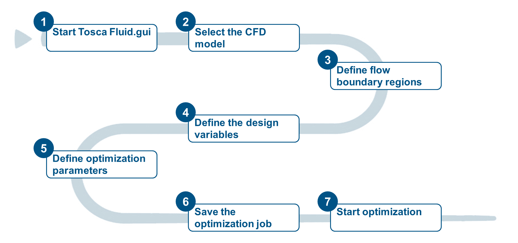
The following figure shows the workflow to set up the optimization of the backstep flow model using the graphical user interface. Afterwards, each of the steps will be described in detail.
Defining the Optimization Problem
Start the Tosca Fluid.gui
in the working directory to define a new optimization problem.
The graphical user interface starts up and the initial screen is displayed as depicted in the figure below.
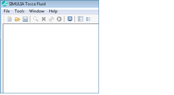
Select File>New Optimization from the menu or click the corresponding icon in the tool bar at the top to create a new optimization problem.
![]()
Selecting the CFD Model
-
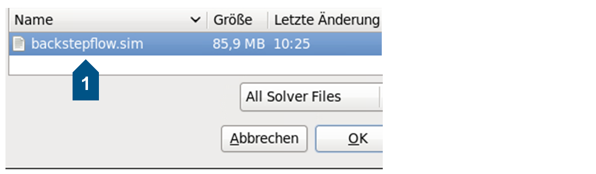
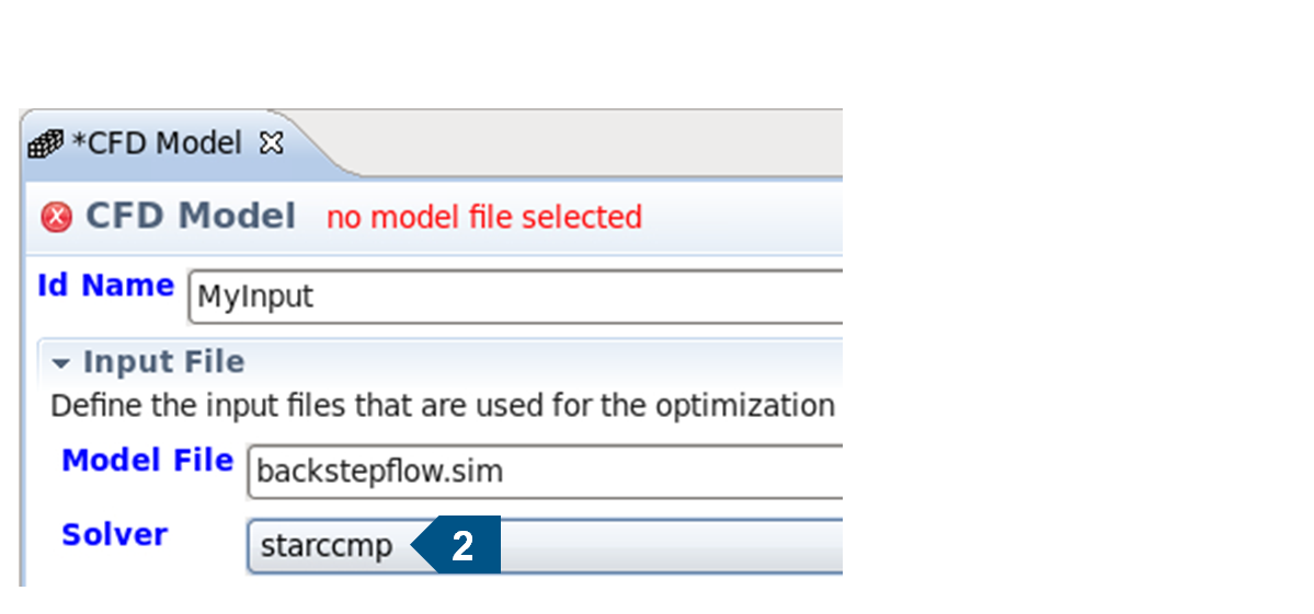
To set the CFD model click the Browse... button and select the simulation file.
-
The model name is now displayed. In the Solver list select the CFD solver that is to be used for the optimization.
![]()
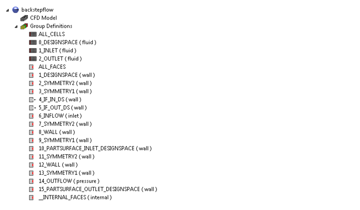
Defining Flow Boundary Regions
All boundaries and regions defined in the CFD model are read automatically. For each entry a respective face or element group is created.
To define the IF_IN_DS boundary as INFLOW, right-click the face group in the job tree and select Set Inflow from the context menu.
In the same way the IF_DS_OUT boundary is defined as an OUTFLOW.
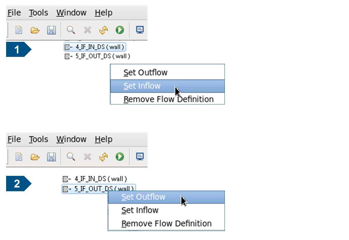
Note: The small icons beside the group entries in the job tree indicate the flow direction with respect to the design space.
![]()
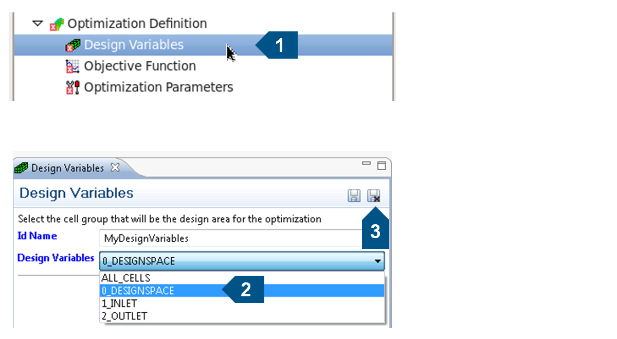
Define Design Variables
To define the design variables, i.e. the group of design cells for the optimization, open the Design Variables panel by double-clicking the entry in the job tree.
Select the cell group named 2_DESIGNSPACE. All cells belonging to this cell zone will therefore be subject to optimization.
Save the settings and close the Design Variables panel by clicking the Save & Close icon in the upper right corner of the panel.
![]()
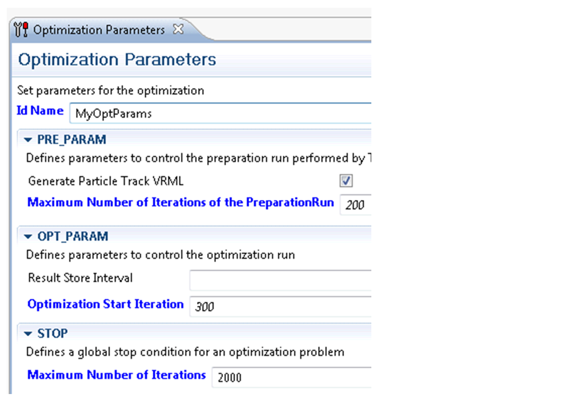
Define Optimization Parameters
To define optimization parameters as well as the stop condition, open the Optimization Parameters panel by double-clicking the entry in the job tree. Here you can set the number of iterations the optimization should run.
![]()
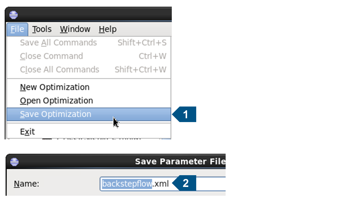
Saving the Optimization Job
Finally the optimization job definition can be saved to the Tosca Fluid XML parameter file. Select File > Save Optimization as depicted in the figure.
In the file system dialog enter backstepflow.xml as the file name.
![]()
Starting the Optimization
Switch to the Tosca Fluid job control section by clicking the green "play button" icon in the toolbar.
Here “–l INFO” is used in the Additional Parameters field to increase the log level and generate a more detailed output in the console.
Start the optimization by clicking Start TOSCA Fluid.
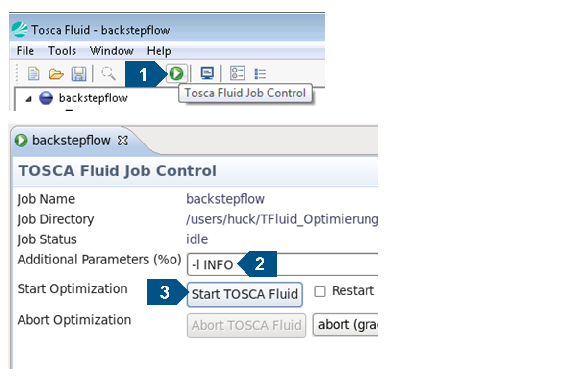
Note: The optimization will take approximately 20 minutes of computation time (1 CPU, depending on the computer system) to finish.
![]()
XML Input File
The xml input file for the optimization is generated automatically by the Tosca Fluid.gui It can also be created or edited manually. The commands are explained in the following.
-
The information about the CFD model
<MODEL_INPUT>
  <ID_NAME>MyInput</ID_NAME>
  <FILE>backstepflow.sim</FILE>
  <SOLVER>starccmp</SOLVER>
</MODEL_INPUT>
-
The declaration which element group belongs to the design variables
<DV>
  <ID_NAME>MyDesignVariables</ID_NAME>
  <ELEMENT_GROUP>0_DESIGNSPACE</ELEMENT_GROUP>
</DV>
-
Creation of a design response, in this case for the backflow.
<DRESP>
  <ID_NAME>DRESP_4_IF_IN_DS_5_IF_OUT_DS</ID_NAME>
  <INFLOW>4_IF_IN_DS</INFLOW>
  <OUTFLOW>5_IF_OUT_DS</OUTFLOW>
  <TYPE>BACKFLOW</TYPE>
</DRESP>
-
Operators are used to combine multiple design responses. In this case we only have one.
<OPERATOR>
  <ID_NAME>MyDrespOperator</ID_NAME>
  <DRESP>DRESP_4_IF_IN_DS_5_IF_OUT_DS</DRESP>
</OPERATOR>
-
The objective function for this optimization.
<OBJ_FUNC>
  <ID_NAME>MyObjectiveFunction</ID_NAME>
  <OPERATOR>MyDrespOperator</OPERATOR>
  <TARGET>MIN</TARGET>
</OBJ_FUNC>
-
The declaration of all flowpaths which exist in the model.
<FLOWPATHS>
  <ID_NAME>MyFlowpathDefinitions</ID_NAME>
  <PATH>4_IF_IN_DS, 5_IF_OUT_DS</PATH>
</FLOWPATHS>
-
Parameters for the preparation run.
<PRE_PARAM>
  <ID_NAME>MyPreParams</ID_NAME>
  <PTRACK_PRIMARY_VRML>YES</PTRACK_PRIMARY_VRML>
  <ITER_MAX>200</ITER_MAX>
</PRE_PARAM>
-
Advanced parameters for the optimization. In this example we do not need to set any.
<OPT_PARAM>
  <ID_NAME>MyOptParams</ID_NAME>
</OPT_PARAM>
-
Advanced parameters for the criterion-based optimization algorithm. Normally it is not required to set anything here.
<ALGO_SET_TOPO_OC>
  <ID_NAME>MyAlgoParams</ID_NAME>
</ALGO_SET_TOPO_OC>
-
The global stop condition for the optimization
<STOP>
  <ID_NAME>MyStopParams</ID_NAME>
  <ITER_MAX>1000</ITER_MAX>
</STOP>
-
Declaration of the complete optimization task. Here we define which of the previously defined commands are actually used for the optimization.
<OPTIMIZE>
  <ID_NAME>MyOptimization</ID_NAME>
  <DV>MyDesignVariables</DV>
  <OBJ_FUNC>MyObjectiveFunction</OBJ_FUNC>
  <PRE_PARAM>MyPreParams</PRE_PARAM>
  <OPT_PARAM>MyOptParams</OPT_PARAM>
  <ALGO_SET_TOPO_OC>MyAlgoParams</ALGO_SET_TOPO_OC>
  <STOP>MyStopParams</STOP>
</OPTIMIZE>
-
Definition of runtime output.
<OUTPUT>
  <ID_NAME>MyVRMLOutput</ID_NAME>
  <FORMAT>WRL</FORMAT>
  <ITERATION>400-1000:100</ITERATION>
  <DESIGN_ONLY>NO</DESIGN_ONLY>
</OUTPUT>